How to Tell If Your Water Softener Is in Bypass
Identify a single or three-valve softener bypass, account for a blending valve, and verify the flow path with a hardness test.
The short answer
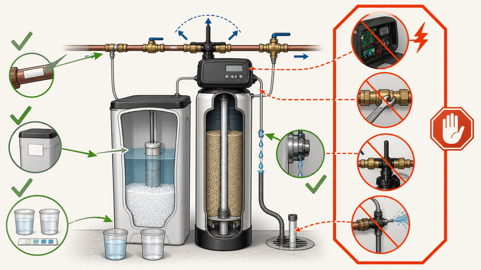
Look at the plumbing, not the salt tank. A single bypass is usually in service when its handle is pulled out and in bypass when pushed in; a three-valve setup is in service with inlet and outlet open and the center bypass closed. A blending valve can intentionally add hardness. Confirm the path with paired hardness samples, and stop if a valve is stuck, leaking, unlabeled, or requires force.How to Tell If Your Water Softener Is in Bypass
If the softener is in bypass, water is routed around the resin tank instead of through it. The fastest safe diagnosis is:
- Identify whether you have a single bypass or three separate valves.
- Read the service/bypass state from the labels, arrows, and flow direction.
- Look for a separate blending valve that can intentionally add hardness.
- Verify the result with paired hardness samples rather than judging how the water feels.
A single bypass is commonly in service when its handle is pulled out and in bypass when it is pushed in, but that is a manufacturer-specific physical convention, not a universal rule. For a three-valve layout, service normally means the inlet and outlet are open and the center bypass is closed; bypass means the center bypass is open and the inlet and outlet are closed. GE’s bypass guide documents both states, and Whirlpool’s manual shows the same two common layouts.
Do not force a handle, loosen a fitting, remove a clip, open an energized control box, or touch live wiring. If the valve is stuck, leaking, unlabeled in a way you cannot resolve, or under obvious pressure, leave it as found and arrange service. A hardness test can tell you what water is coming out; it cannot make an unsafe valve safe to operate.
1. Start with the flow-path question
The question is not “Does the softener look switched on?” It is “Can incoming water reach the softener inlet, pass through the treatment media, and leave through the outlet?” A powered display, a full salt tank, or a regeneration history does not answer that flow-path question.
The bypass exists so the softener can be isolated while the home still has water. GE describes a bypass as a way to turn off water to the softener for maintenance while keeping water in the house pipes. That means a bypass position may leave every faucet running normally. It can look like a working water supply while the softener is doing no treatment.
Begin at the equipment without changing anything. Record:
| Observation | What it can tell you | What it cannot prove |
|---|---|---|
| The control head has one large push-pull or T-shaped handle | The installation may use a single bypass | The current state, unless the label or manual confirms the direction |
| Three separate shutoff-style valves are piped around the tank | The installation may use a three-valve bypass | Which valve is inlet, outlet, or bypass until you trace flow |
| A small adjustment or hex nut sits beside the bypass | The unit may have a blending valve | Whether it is open, closed, or leaking internally |
| The display is lit and the salt level is present | The controller has power and the brine tank contains salt | Whether water is passing through the resin tank |
| Water feels slippery or not slippery | A subjective sensation that may change with soap, temperature, and water chemistry | A reliable hardness result; Rheem specifically recommends testing instead of judging by feel |
| Hardness is high at a downstream tap | The water was not softened enough at that sampling point | Whether the cause is bypass, exhausted capacity, wrong programming, blending, channeling, or a failed control valve |
The last distinction prevents a common wrong turn. A hard result is evidence about the water at the tap, not a diagnosis of the valve. You need the valve layout and a comparison sample before assigning the cause.
Keep untreated and treated locations separate
Look for a faucet or pipe that is clearly labeled untreated, raw, well, or before treatment. Some homes have outside faucets or a dedicated hose bib upstream of treatment; others do not. Do not assume an outdoor faucet is untreated just because it is outside. Trace the plumbing or rely on a clearly labeled installation diagram.
If there is no known untreated sampling point, you can still record a downstream hardness result, but call it a single-point observation. Do not claim that the softener passed or failed from that number alone.
2. Classify the bypass arrangement
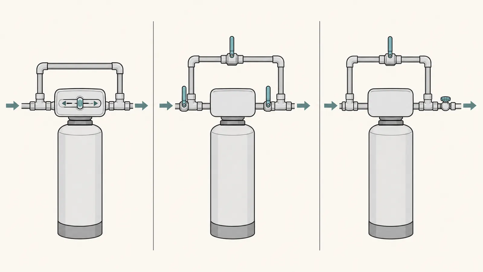
This guide covers three common patterns, but an inherited installation may use another design or a combination. If the plumbing does not match one of the patterns below, stop and treat it as unknown rather than forcing a classification or operating a valve. The first two are bypass layouts. The third is a caveat that can make a correctly positioned softener deliver some hardness by design.
Single bypass: one control at the softener head
A single bypass is integrated into or immediately beside the softener’s control head. It may look like a slider, stem, T-handle, or cone-shaped handle. The important feature is not the shape; it is that one control changes the route between service and bypass.
On the documented GE and Rheem examples, the normal service state is the handle pulled out, and pushing it in sends water around the softener. Rheem says its pulled-out position means the softener is being used and its pushed-in position means water is skipping the unit. Rheem’s support article shows those states for its own single-bypass assembly. Whirlpool’s WHES40/WHES44 manual likewise labels pull-out as “Service” and push-in as “Bypass.”
Treat those directions as a strong clue, not permission to push an unknown valve. Before touching it, look for:
- molded or printed words such as
SERVICE,BYPASS,IN, orOUT; - an arrow showing the direction of water flow;
- the equipment model number and matching owner’s manual;
- a handle that is fully seated rather than halfway between positions;
- wetness, mineral tracks, cracks, or a spray around the valve body.
If the handle is between labeled positions, that is not a third operating mode you should interpret from appearance. A partially moved valve can restrict flow or leak. If it will not move with light, steady hand pressure, stop.
Three-valve bypass: two valves to the tank and one shortcut
A three-valve layout uses three individual valves. The inlet valve controls water entering the softener. The outlet valve controls water leaving it. The third valve connects the incoming side to the outgoing side, creating a shortcut around the tank.
The standard state table is:
| Desired flow path | Inlet valve | Outlet valve | Center bypass valve | Interpretation |
|---|---|---|---|---|
| Service through the softener | Open | Open | Closed | Water is offered a path through the resin tank |
| Bypass around the softener | Closed | Closed | Open | Water takes the shortcut and skips treatment |
| Unclear or transitional | Partly open or unknown | Partly open or unknown | Partly open or unknown | Do not infer; identify the valves or call for service |
This is the flow logic documented by GE for a three-valve bypass and by Rheem for its three-valve arrangement. “Open” and “closed” refer to the valve’s actual flow state, not always the handle’s position relative to the wall. Ball-valve handles often align with the pipe when open, but do not rely on that visual convention if the valve type or plumbing is unfamiliar.
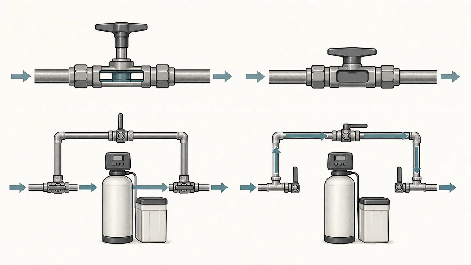
The safe identification sequence is to follow the pipe, not to guess from left and right. Find the incoming main, see which pipe enters the softener valve, and find the pipe leaving toward the house. Whirlpool instructs installers to trace water flow and make sure the hard-water supply reaches the softener inlet. That matters because a reversed or unusual installation can make a familiar handle arrangement misleading.
If you cannot confidently identify all three valves, do not test the layout by closing random valves. An unlabeled three-valve system is a documentation problem, not a puzzle that should be solved by trial and error while the pipes are pressurized.
A control valve is not the same thing as a bypass valve
The large valve head on top of the resin tank may have a display, motor, regeneration positions, and a drain connection. Do not manually rotate a cam, open the cover, or advance an energized mechanism just to determine whether the softener is in bypass. The bypass is the external plumbing control; the controller’s cycle position is a separate question.
3. Read the valve state without creating a new problem
Once you have classified the layout, use a three-pass inspection.
Pass one: labels and arrows
Take a photo of the entire installation and a close photo of each valve. Record every visible label exactly, including abbreviations. If the unit has a model and serial label, record those too. The model number is more useful than the brand name alone because bypass designs can change across product generations.
For a single bypass, a clear SERVICE or BYPASS mark is decisive if the handle is fully at that mark. For three valves, labels such as IN, OUT, and BYPASS are more important than where the handles point. If a label conflicts with your assumed flow direction, stop and document the conflict.
Pass two: visible condition
Look for active dripping, a bead of water forming, a wet floor, white or green mineral tracks, a cracked plastic body, or a pipe that is visibly stressed. Do not wipe away a leak and then operate the valve to see whether it returns. A leak can be small and still be under pressure.
You may observe the pressure gauge if one is plainly visible and readable. Do not remove a gauge, loosen a union, pull a clip, or open a cover. Whirlpool’s installation manual includes an electrical-shock warning and says plumbing must be depressurized before a bypass clip is removed; those instructions are a clear boundary for homeowner diagnosis.
Pass three: state consistency
Ask whether the apparent state makes a coherent path. Examples:
- A single handle marked
BYPASSand visibly pushed in is consistent with bypass. - Three valves marked
IN,OUT, andBYPASSwith inlet and outlet closed and center bypass open are consistent with bypass. - Three valves that are all partly open are not a valid conclusion; they are an unknown state that may be transitional or poorly adjusted.
- A blending adjustment that is open can produce some hard water even when the main bypass is in service.
Do not infer from sound alone. A softener may click, hum, or remain silent depending on whether it is metering or regenerating. Those observations can support a service call, but they do not establish the flow path.
4. Check for a blending valve before calling the main bypass wrong
A blending valve is a separate control that mixes a small amount of untreated water into the softened outlet. It is intended to adjust the hardness of product water, not to provide the same all-or-nothing shortcut as the main bypass.
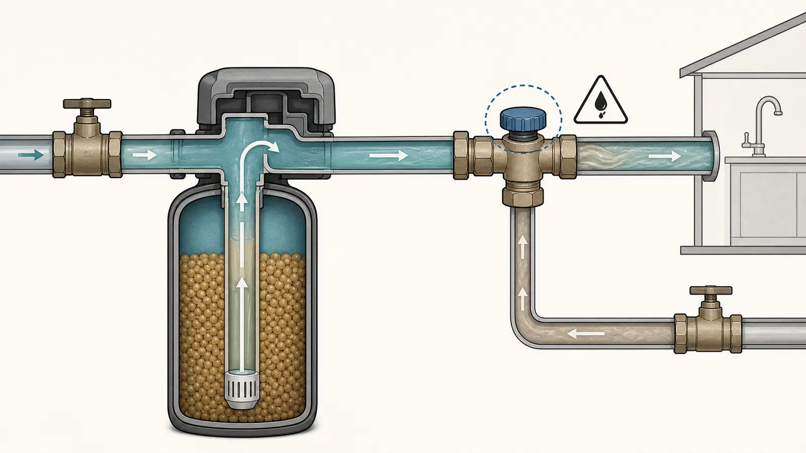
Rheem describes a blending valve on the side opposite the bypass handle. In its assembly, turning the adjustment counterclockwise opens the blend and adds hardness; turning it clockwise closes the blend. Rheem also warns that turning it too far can unscrew the valve and cause a leak. Read Rheem’s blending-valve instructions as a model-specific example, not as a universal adjustment procedure.
For an inherited or unlabeled system:
- Photograph the blending control in its original position.
- Record whether it has a locknut, cap, arrow, scale, or model-specific label.
- Do not unlock or turn it to “see what happens.”
- Use the hardness test to determine whether the outlet is harder than expected.
- Ask a service professional to identify the adjustment range if the control is unlabeled or wet.
A blending valve changes the interpretation of the verification test. A moderate hardness result does not automatically mean that the main bypass is open. It may mean that the resin is working and a blending path is open, or that the system has another water source or treatment issue. The hardness result must be read alongside the valve layout.
5. Verify the path with a paired hardness test
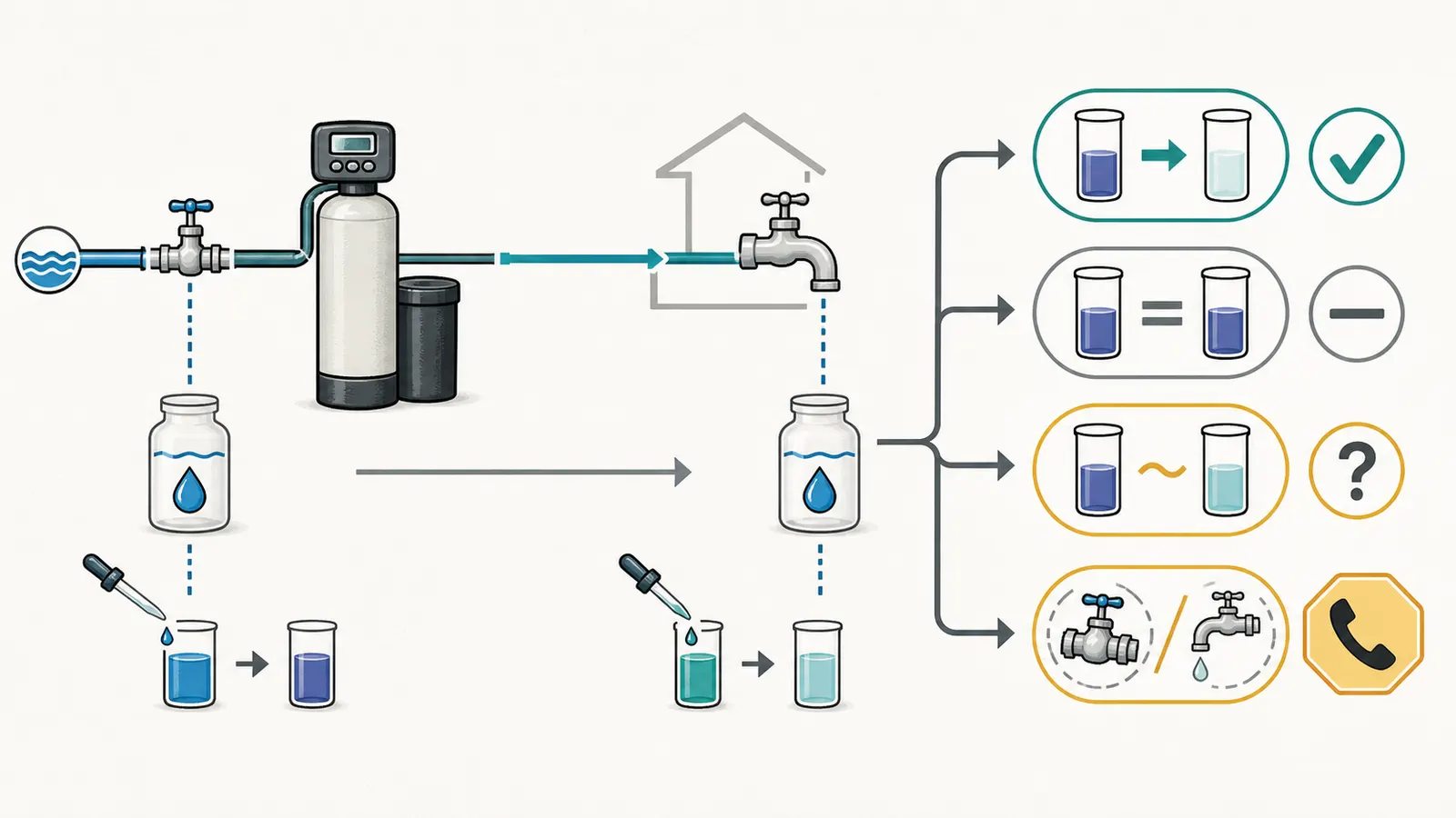
The reliable homeowner check is comparative: measure a known untreated sample and a downstream sample under comparable conditions. Rheem recommends using a hardness strip after a recharge and testing at several faucets, while also cautioning homeowners not to judge operation by how water feels. Its support workflow gives the test-based rationale and its own soft-water reference range.
Rheem’s 0–3 grains per gallon or 0–50 ppm reference is specific guidance from that manufacturer. Do not convert it into a universal pass/fail rule for an unknown unit. A better model-neutral question is: does the downstream result show a meaningful reduction compared with the known untreated source, and is that reduction consistent across repeat samples?
Procedure
Use a hardness kit or strips that report the unit used by the manufacturer or laboratory—commonly grains per gallon (gpg) or parts per million (ppm). Follow the kit’s sample volume, waiting time, and color-reading instructions. Do not compare a strip read immediately with another strip read after a different waiting time.
- Choose the locations. Select a clearly known untreated tap if one exists and one cold faucet downstream of the softener. If you have several downstream faucets, include one near the equipment and one farther away. If no untreated point is known, label the result “single-point downstream observation.”
- Control the conditions. Test at roughly the same time, with no regeneration in progress and no other large water use. Record the date, time, faucet, temperature category, kit brand, unit, and result. Do not use a hot-water result to represent the incoming cold-water path; the water heater is a separate storage and distribution step.
- Flush consistently. Run each tap according to the test kit’s instructions, using the same approach for the comparison samples. Do not invent a flush time or volume when the kit does not specify one; consistency is more useful here than a made-up precision.
- Test the untreated sample. Record the result before testing the downstream point. If the untreated point is not truly upstream, do not call it untreated in the log.
- Test the downstream sample. Use the same kit and read it at the prescribed time. Record the result without rounding beyond the kit’s available increments.
- Repeat once. A repeat on another day or at another downstream cold faucet helps distinguish a stable flow-path result from a sample, strip, or plumbing anomaly.
- Compare the pattern. A clear reduction downstream supports water passing through a working softening path. Similar high results at both points support “no demonstrated reduction,” not a specific valve diagnosis. A mixed result calls for checking blending, regeneration, sample location, and equipment condition.
Use this log while testing:
| Date/time | Sample point | Expected path | Hardness result | Unit | Valve state observed | Notes |
|---|---|---|---|---|---|---|
| Known untreated / unknown | Before softener / uncertain | gpg or ppm | ||||
| Downstream cold faucet | After softener | gpg or ppm | ||||
| Repeat downstream point | After softener | gpg or ppm |
How much reduction is enough?
Do not manufacture a universal cutoff from an unlabeled system. The result depends on the unit’s intended capacity, the incoming hardness, the test method, iron or manganese, the timing of regeneration, and whether blending is intentional. Whirlpool’s manual, for example, tells owners to program hardness and separately discusses iron compensation; that is one reason a simple strip result should not be used to infer resin failure or a wrong setting. The Whirlpool manual’s hardness and iron notes are here.
For the bypass question, the most useful outcomes are directional:
- Untreated high, downstream materially lower: treatment flow is demonstrated at that sampling point. The main bypass is unlikely to be fully open at the time of the sample, although a blending valve or another plumbing branch may still affect the result.
- Untreated and downstream similar: no meaningful reduction was demonstrated. Recheck the sampling points and valve identification before blaming salt, resin, or the controller.
- Downstream varies from faucet to faucet: investigate plumbing branches, a blending valve, a point-of-use device, hot-versus-cold differences, or inconsistent sampling. This is not a clean bypass diagnosis.
- All samples are unexpectedly low or high: preserve the log and ask for water-quality or equipment evaluation. A hardness strip does not assess every contaminant or every softener function.
6. Interpret the result with a diagnostic matrix
The table below keeps the flow-path conclusion separate from the next troubleshooting branch.
| What you observe | Most defensible interpretation | Do not infer | Safest next step |
|---|---|---|---|
Single bypass clearly marked BYPASS; downstream hardness matches untreated water | The unit is visibly in bypass, if the label belongs to that valve and the valve is fully seated | That the resin or controller has failed | Photograph the state, then use the matching manual or have a professional return it to service if the valve is safe to move |
Single bypass clearly marked SERVICE; downstream hardness is materially lower than untreated water | Service flow is supported by both position and measurement | That the salt setting, capacity, or regeneration schedule is correct | Record the result and monitor; investigate only if hardness later rises |
| Three valves: inlet and outlet closed, center open; downstream matches untreated | The shortcut state is consistent with bypass | That all three valves are correctly labeled if labels are missing | Do not cycle an unlabeled setup; obtain the installation diagram or service |
| Three valves: inlet and outlet open, center closed; downstream is lower | Service flow is supported | That the system is operating at rated capacity | Keep the log and check the unit manual for settings and maintenance |
| Main bypass appears in service, but a separate blend control is open | Some hardness may be intentional mixing | That the main bypass is open | Do not adjust an unknown blend valve; have it identified and set to the household’s target |
| Handle is stuck, valve body is wet, or a fitting is leaking | The installation needs a safe repair assessment | That more force or a tighter fitting will fix it | Leave the valve alone, protect the area from water damage, and call a qualified water-treatment or plumbing professional |
| Hardness results conflict between samples | The sampling path or treatment state is not yet established | That the softener is definitely bypassed or definitely broken | Repeat only at clearly identified points; otherwise hand off the log and photos |
Pentair uses a related isolation idea for pressure complaints: if pressure improves in bypass, the restriction may be within the treatment system; if it does not, the restriction may be elsewhere in the plumbing. That is a pressure diagnostic, not a hardness test. Do not use a pressure improvement in bypass as proof that the softener is correctly softening water.
7. Know when the answer is “call for service”
Before any repair, re-plumbing, electrical work, or water-quality decision, stop and check the requirements that apply where you live. Local plumbing, electrical, water-quality, licensing, and permit rules can vary by jurisdiction, private-well status, and the equipment involved. Confirm the boundary with the relevant local authority or a qualified professional before changing the installation or acting on a water-quality result.
A homeowner can safely observe labels, handle position, pipe routing, visible leaks, model information, and hardness-test results. The boundary changes when the next step would involve stored pressure, electrical energy, disassembly, or an unknown valve design.
Stop and arrange qualified help if any of these apply:
- the valve will not move with light hand pressure;
- the handle or body is cracked, wet, bulging, or actively leaking;
- the three valves are unlabeled and you cannot trace inlet, outlet, and bypass;
- the plumbing appears reversed, unsupported, or stressed;
- the adjustment may be a blending valve but has no readable instructions;
- you would need to remove a clip, union, cap, gauge, drain connection, or valve cover;
- you would need to open an electrical enclosure, test live wiring, or work near a wet outlet;
- the water softener is in a crawlspace, pit, tank room, or other confined or poorly ventilated space;
- the home has a private well and the symptom includes loss of supply, pump cycling, or uncertain water quality;
- a leak cannot be contained without shutting a main valve whose function you do not understand.
For moderate-risk diagnosis, this is a hard stop: do not open energized controls, test live wiring, open a well, pull a pump, enter a confined space, or manipulate pressurized equipment unless the exact action is clearly covered by the equipment manual and is demonstrably safe. In an inherited installation, that standard is rarely met by a visual guess.
Give the professional a compact handoff instead of a verbal theory:
- Brand, model, serial number, and approximate installation date if known.
- One wide photo showing the tank, control head, brine tank, and all bypass plumbing.
- Close photos of every handle, label, arrow, blending adjustment, gauge, and visible leak.
- A sketch showing the incoming pipe, softener inlet, softener outlet, house direction, and any upstream or downstream treatment.
- The valve state as found; do not change it just before the visit.
- The hardness log, including test kit, units, sample points, dates, and whether the point was known untreated.
- The symptom: hard-water test, low pressure, leak, salt not changing, failed regeneration, or a combination.
The practical conclusion is narrow but useful: a clear service or bypass position tells you the intended route, while paired hardness results tell you whether the observed water behaves as if it passed through treatment. If those two pieces disagree, do not jump to salt, resin, or control-valve failure. Resolve the layout, blending, sampling, and safety questions first.
Sources and scope
Evidence behind this page
- GE Appliances — Water Softener: Bypass Options
GE's general support explanation of bypass purpose; it describes common softener arrangements and is not a code requirement for every installation.
- GE Appliances — Water Softener: Bypass Options
GE's single-bypass description; other brands and valve generations may use different shapes, labels, or motions, so the article presents this as a recognizable pattern rather than a universal physical rule.
- GE Appliances — Water Softener: Bypass Options
GE's three-valve flow-state description; it applies when the valves are correctly identified and the arrows or plumbing direction match the installation.
- Rheem Water Treatment — How Does a Bypass Valve Work?
Rheem's own single-bypass assembly; the handle direction should not be copied to an unlabeled valve without matching the equipment manual or visible labels.
- Rheem Water Treatment — How Does a Bypass Valve Work?
Rheem's blending-valve design and operating limits; the article uses it to explain the caveat, not to prescribe adjustment of another brand's valve.
- Rheem Water Treatment — How Do I Know If My Softener Is Working?
Rheem's support workflow and stated range; the numeric range is retained as Rheem's brand guidance, not a universal pass/fail threshold for every softener, water chemistry, or test method.
- Whirlpool Water Solutions — WHES40/WHES44 Demand Controlled Water Softener Installation and Operation Manual
The cited Whirlpool models and manual diagrams; it confirms the cross-brand pattern but does not identify every possible softener valve design.
- Whirlpool Water Solutions — WHES40/WHES44 Demand Controlled Water Softener Installation and Operation Manual
Whirlpool's installation instruction for its softener valve; the article applies the flow-direction principle to unlabeled installations without asserting that every home has the same left-right orientation.
- Whirlpool Water Solutions — WHES40/WHES44 Demand Controlled Water Softener Installation and Operation Manual
Safety warnings and service instructions in the Whirlpool manual; the article extends the stop boundary to an inherited or unlabeled installation where the exact equipment and hazards are unknown.
- Pentair — Residential Filtration FAQs
Pentair's FAQ for its filtration products; this is a supporting interpretation for pressure symptoms, not proof that hardness treatment is working or that a particular valve state is correct.