Can a Water Softener Regenerate With a Low-Flow Well Pump?
Use the softener model, regeneration-stage flow, pressure, pressure-tank drawdown, and measured well output to decide if regeneration is reliable.
The short answer
Yes, but only if the exact valve can complete its highest-flow regeneration stage at the required pressure. Find the model manual, measure loaded flow and running pressure at the softener inlet, and compare sustained output—not just a pump label—with the valve's backwash requirement. A pressure tank can bridge a short demand; it cannot create water a low-yield well does not produce. Stop before changing pressure-switch settings.Can a water softener regenerate with a low-flow well pump?
Yes—sometimes. The deciding comparison is not the pump’s horsepower, the softener’s advertised grain capacity, or the number on the pressure tank. It is:
the exact softener valve’s highest-demand regeneration flow and minimum operating pressure versus the well system’s measured, sustainable delivery at the softener inlet.
For a private well, treat these as separate questions. A cation-exchange softener uses water and salt during regeneration to flush excess ions and recharge the resin, as explained by the U.S. EPA cation-exchange overview, so the regeneration demand is a real water-system load rather than a controller-only event.
- Can the valve move through every regeneration stage without falling below its pressure requirement?
- Can the well replenish the water used during the high-flow stage for as long as that stage lasts?
- Is the softener installed after the pressure tank, with a drain that can accept the flow?
A pressure tank may bridge a short demand with its usable drawdown. It cannot manufacture water. If the well yields less than the regeneration stage for long enough, pressure will eventually fall, the cycle may stall or fail, and the pump may be stressed. Do not change a pressure-switch cut-in/cut-out setting, bypass a low-water safety, open an energized control box, or force a regeneration to “see what happens.” Use the model manual and a qualified well or water-treatment professional when the numbers do not clearly align.
Start with the exact valve, not the softener label
“A 32,000-grain softener” is not enough information to answer this question. Grain capacity describes how much hardness the resin can exchange under a particular salt setting and operating program. It does not tell you the backwash flow, minimum pressure, drain requirement, or whether the valve is configured for your resin-tank diameter.
Find the model and control-valve identification before comparing flow. Look for a label on the valve body, controller, tank rim, underside of the salt lid, installation invoice, or owner’s manual. Record all of the following:
| Field to record | Why it matters | Where to find it |
|---|---|---|
| Valve brand and exact model | Manuals and flow tables are model-specific | Valve label, manual, installer record |
| Controller and regeneration direction | Upflow and downflow programs can use different paths | Controller display and manual |
| Resin-tank diameter and height | Backwash flow is tied to bed expansion and tank geometry | Tank label, invoice, manual |
| Backwash or drain-line flow-control value | This is often the regeneration-stage demand to compare | Valve manual, flow-control label |
| Minimum and maximum pressure | A cycle can fail even when some water is flowing | Installation manual |
| Service-flow rating and pressure drop | Normal household use is a separate hydraulic check | Technical data sheet |
| Regeneration-stage duration and total water | Tells you whether the tank is a brief buffer or an inadequate supply | Cycle programming table |
| Drain-line size, length, and air gap | A regeneration can fail because the drain path is restricted | Installation instructions |
One Pentair example shows why model-first research matters. Pentair lists the Fleck 5800 valve at 21 gallons per minute (GPM) continuous service flow and 17 GPM backwash flow, with backwash capability for softener or filter tanks up to 16 inches in diameter. Those are specifications for that valve family, not a universal rule for every residential softener. A smaller valve, a different injector, an upflow configuration, or a different tank may have a different requirement. Read the exact table that matches the proposed or installed configuration in the Fleck 5800 valve specifications.
The pressure requirement is equally concrete. The Fleck 5800 SXT manual states that at least 20 psi is required for the regeneration valve to operate effectively and cautions that pressure must not exceed 125 psi. That does not mean every softener needs exactly 20 psi, nor does it mean 20 psi is comfortable operating pressure for every house. It means that a proposal using this valve must show how the system will stay within that manual’s limits during regeneration.
Separate service flow from regeneration flow
Service flow is the flow through the resin tank while the household uses softened water. Regeneration is a sequence that may include backwash, brine draw and slow rinse, rapid rinse, and brine-tank refill. The control valve changes the hydraulic path between those stages. The peak requirement may occur during backwash, but you must confirm that in the manual rather than assume it.
A valve can serve a shower at a satisfactory flow and still fail to backwash its resin bed. Conversely, a well that can deliver the backwash rate may still have a pressure loss, clogged prefilter, undersized drain, or inadequate service-flow rating. Put both comparisons on the worksheet:
| Comparison | Pass question | Do not infer |
|---|---|---|
| Service flow | Does the valve and plumbing provide the needed simultaneous fixture flow at acceptable pressure? | That a high service rating proves regeneration will work |
| Highest regeneration flow | Does measured supply meet the exact backwash or other highest-demand stage? | That “it fills the brine tank” proves the high-flow stage works |
| Minimum pressure | Does pressure remain above the manual’s minimum while the stage is running? | That static pressure at a closed faucet equals running pressure |
| Duration and volume | Can the well replenish the demand for the complete stage? | That a larger nominal pressure tank solves a sustained shortfall |
| Drain capacity | Can the drain line accept the required flow without backpressure or an unsafe discharge? | That a nearby drain is automatically adequate |
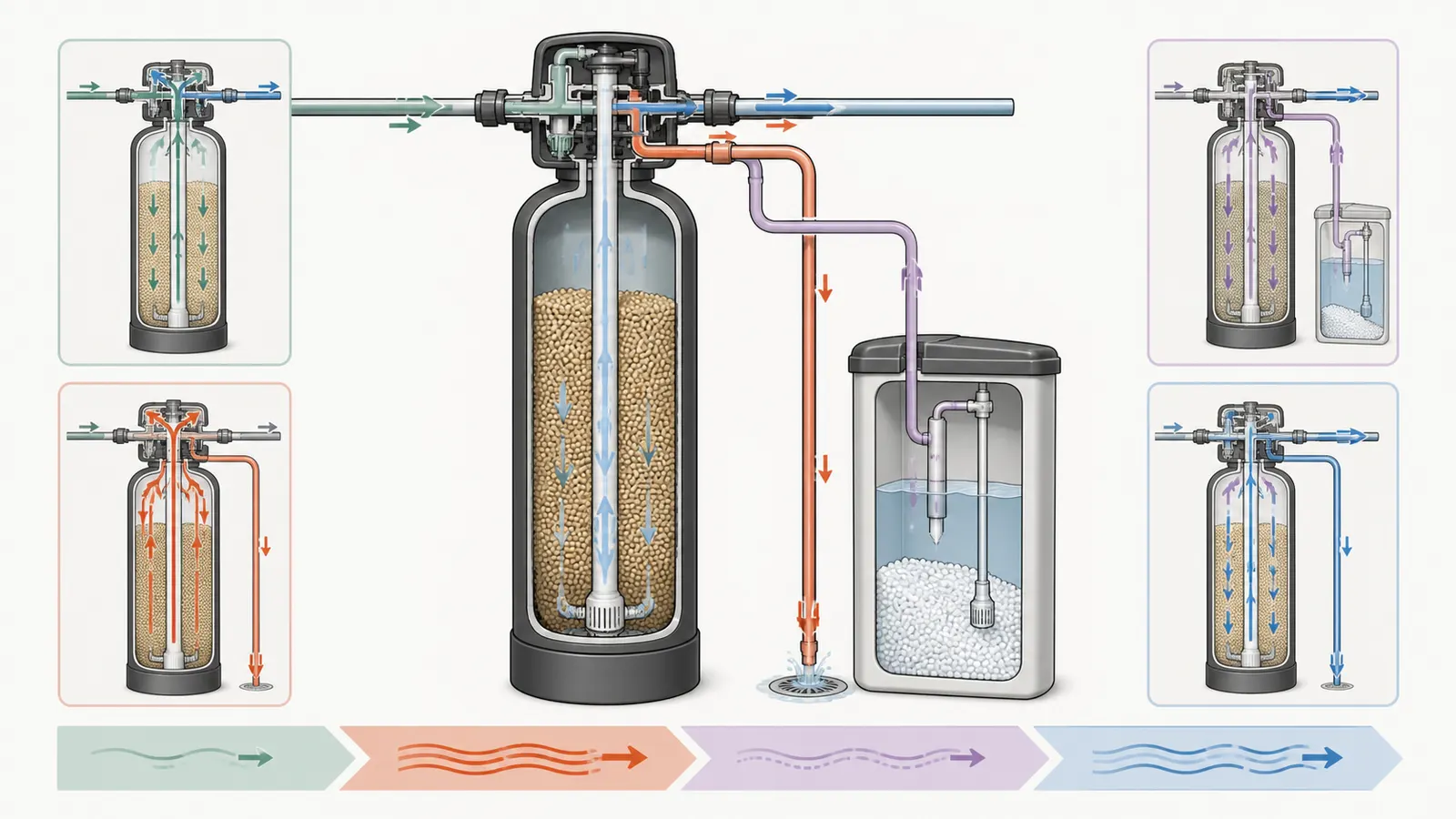
Do not use a universal 5 GPM or 50-to-100-gallon rule as a pass/fail cutoff. EPA notes that softeners can consume significant water and salt during regeneration, but the exact valve, injector, tank diameter, programming, and flow-control parts determine the installed demand. Use the EPA cation-exchange overview for the general process, then use the exact valve manual for the numbers. Record every stage’s flow-control value, duration, and total water so a low-yield system is compared with the equipment actually proposed.
Install the softener after the pressure tank
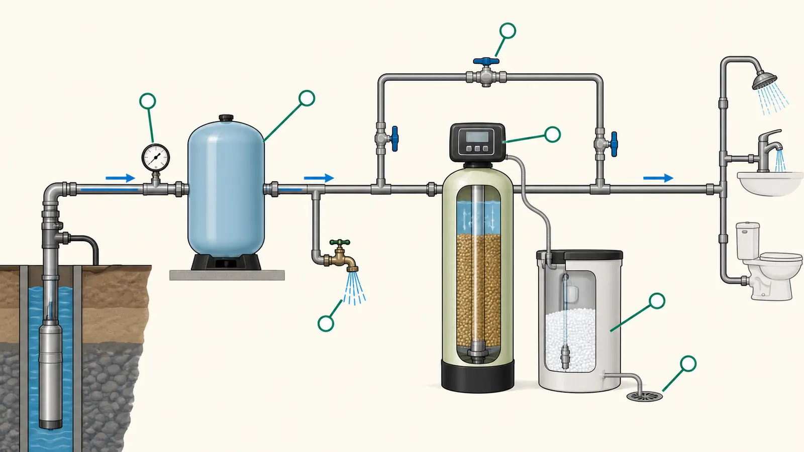
For a well system, the normal order is well pump, pressure tank, softener, then house distribution. Keep outdoor hose connections and other lines that do not need softened water on the appropriate untreated branch if the plumbing design allows it.
Rheem’s private-well installation guidance says the softener should always be downstream of the pressure tank. It gives three reasons: an upstream softener receives water only when the well pump is running rather than a steadier supply from the tank, regeneration could send water backward through the valve outlet toward the pressure tank, and a clogged treatment unit could contribute to pump short-cycling.
That placement advice does not turn the pressure tank into a permanent storage reservoir. It gives the treatment equipment access to the water already stored under pressure and lets the pump controls operate as designed. It also creates a sensible point for pressure and flow measurements: the tank outlet or a nearby faucet before the softener, followed by a check at the softener inlet if there are filters, long runs, or other restrictions between them.
What the pressure tank can and cannot do
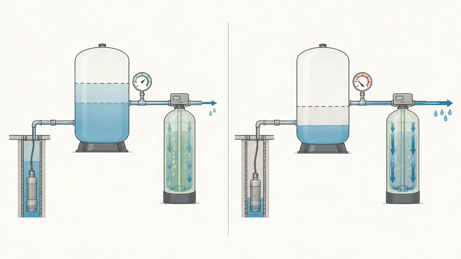
The pressure tank stores water under pressure and reduces how often the pump starts and stops. The usable quantity between pump shutoff and pump start is called drawdown; it is much smaller than the tank’s labeled gallon capacity. Connecticut Department of Public Health private-well guidance warns that pressure tanks have very little usable volume compared with their total size and that small usable volume can contribute to pump short-cycling. Use the Connecticut private-well safe-yield guidance as context, but take the actual drawdown from the exact tank chart, pressure band, or professional test.
This gives you a useful mental model:
Available water during a short demand ≈ verified pressure-tank drawdown + water delivered by the well while the pump runs.
If the softener backwash requires 10 GPM and the well sustains only 2 GPM, a tank with 8 gallons of usable drawdown can cover the difference for roughly 60 seconds in a simplified calculation:
8 gallons ÷ (10 GPM − 2 GPM) = 1 minute
That calculation is a screening estimate, not a permission to run a regeneration. Real pressure falls, pump output changes with pressure and water level, and the valve may stop working before the tank is empty. The point is to show why a “large” tank can buffer a short event but cannot cover a 20-minute deficit.
When storage is the right conversation
An EPA small-water-system manual distinguishes a pressure tank’s limited reserve from intermediate storage: if the well and pump cannot supply the peak demand for the intended period, an intermediate storage tank can receive water at the well’s safe continuous yield and feed the pressure system. The EPA small-water-system manual describes that arrangement as an engineering option, not a universal private-well prescription.
That is a system redesign, not a bigger softener tank. It may involve a nonpressurized storage tank, a second pump, level controls, low-water protection, treatment compatibility, disinfection, freeze protection, and local requirements. Ask a qualified well-system professional to design it. Do not improvise a storage tank, reconnect pressure piping, or change controls based on a softener salesperson’s estimate.
Measure supply without disturbing the well controls
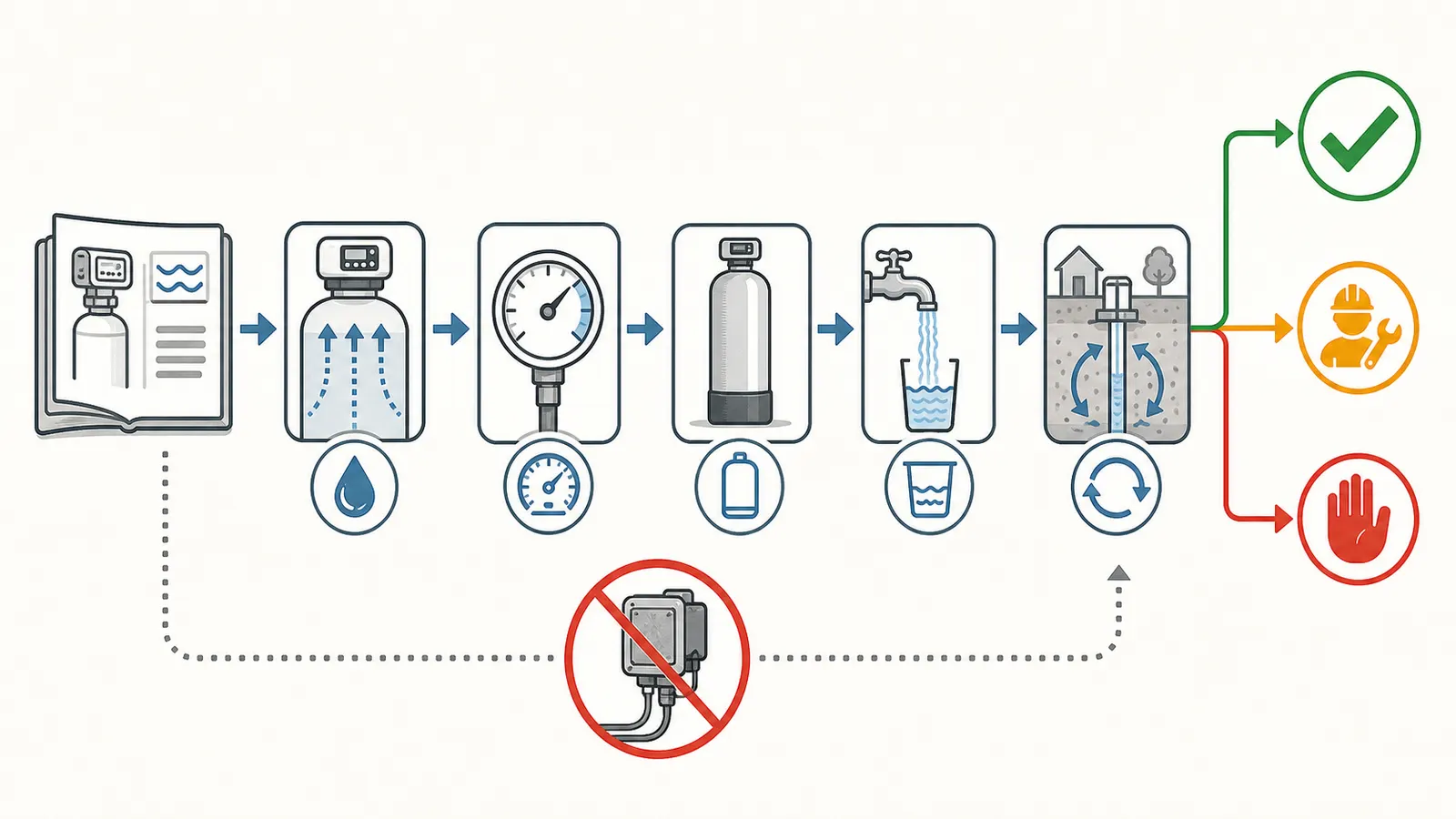
The homeowner-safe objective is to document pressure and flow at accessible fixtures. You are not trying to prove the pump’s theoretical horsepower or diagnose the well by opening the casing. You are trying to create a repeatable field record that a professional can compare with the softener manual.
Gather the documents and safe tools
Collect:
- The softener model, valve model, resin-tank diameter, and manual.
- The well completion report or prior yield test, if available.
- Pump make and model, but do not treat its nameplate rating as delivered flow.
- Pressure-switch cut-in and cut-out values only as recorded from existing labels or paperwork; do not adjust them.
- Pressure-tank manufacturer, nominal size, and drawdown chart if available.
- A hose or fixture that can discharge to a safe location.
- A container of known volume and a stopwatch, or an installed flow meter.
- A non-invasive hose-thread pressure gauge if you know how to attach it to a faucet without opening a pressurized component.
- A notebook or phone log with date, time, weather, tank pressure, flow, and observations.
Do not open the pressure-switch cover, electrical panel, pump control box, well cap, or any energized control. Do not pull a pump, enter a pit or confined space, disconnect pressurized piping, or manipulate the pressure tank’s air valve or precharge as part of this homeowner comparison. Have a qualified well contractor perform tests that require access to the well, pump wiring, pressure controls, or pressurized equipment.
Record static and running pressure
- Record the test locations before opening water: the pressure-tank outlet or pre-softener point, and the softener inlet immediately upstream of the control valve. A pressure reading far downstream may include filter, pipe, elevation, or treatment losses. If there is no safe inlet gauge or test port, have the installer measure it; do not loosen pressurized fittings.
- With no water running, record the gauge reading and whether the pump is on or off. This is static or near-static pressure, not the regeneration result.
- Open the faucet to a steady, safe discharge. Record the initial pressure, the pressure after 30 seconds, and the lowest observed pressure during a two- to five-minute observation. Record the running pressure at the softener inlet at the same times when that point can be measured safely.
- Note when the pump starts and stops if those events are visible or audible without touching controls. Do not force a cycle and do not run the fixture until the well runs dry.
- Repeat on a second day or at the time of day when household demand is normally highest. A single quiet-day reading can overstate the available supply.
The Rheem pressure-testing guide recommends checking incoming pressure near the well pressure tank for well water and lists 20 to 125 psi for its systems, with a recommended ideal range of 50 to 70 psi. Use that as Rheem-specific guidance, not a national rule. For another valve, use its manual.
Measure accessible flow
Use the container method only at a faucet or hose bib where the discharge is safe and does not flood the well room, electrical equipment, septic area, or foundation. If a flow meter is already installed, record its reading and location.
For a container:
- Measure the container’s actual volume. Do not assume a bucket is five gallons.
- Open the fixture to the test position and let the flow stabilize.
- Collect water for a timed interval, such as 30 seconds.
- Convert to GPM:
gallons collected × 60 ÷ seconds collected. - Repeat three times and record the range, not only the highest value.
For example, 4.5 gallons collected in 30 seconds equals 9 GPM at that fixture. If the pressure fell from 58 psi to 34 psi during the collection, write both numbers down. The 9 GPM is not proof that the well can sustain 9 GPM indefinitely; it is a point-in-time delivery measurement under that system condition. For the purchase decision, repeat the measurement at the softener inlet or have a professional measure there under load, and record the inlet location, valve position, other water use, date, time, and test duration.
Use this rule for the exact regeneration stage. Let Q_stage be the manual’s highest required regeneration flow, P_min its minimum operating pressure, and T_stage the full duration of that stage. The proposed setup passes the direct inlet screen only when loaded inlet flow is at least Q_stage and running inlet pressure stays at or above P_min for every reading throughout T_stage. If the well’s sustainable rate Q_well is lower, a storage-credit calculation is only a professional design check: deficit volume = max(0, Q_stage − Q_well) × T_stage. Verified usable drawdown must cover that deficit, and inlet pressure must still remain above P_min for the full stage. If either condition is unknown or fails, mark the proposal unresolved or incompatible; do not force a regeneration.
Do not run the softener’s regeneration as the field test unless the exact manufacturer procedure says it is safe and a professional has confirmed the well has sufficient water. A failed regeneration can leave the home with hard water, create a drain-discharge problem, or expose an already weak pump system to unnecessary stress.
Test recovery, not just the first minute
The most important unknown is often recovery: how the water level and pressure behave after several minutes of continuous demand. A homeowner should not lower a probe into the well or perform a formal pump test. Instead, give the professional your accessible records and ask for a controlled flow-and-recovery test using appropriate equipment.
The EPA small-water-system manual explains that yield and drawdown testing uses a predetermined pumping rate, records water level and maximum drawdown, then observes recovery after pumping stops. It says reliable testing should be performed by competent drillers or engineers. That is why a pump nameplate, a one-minute bucket test, or a brief pressure spike cannot substitute for a well-yield or recovery assessment when the numbers are close.
Use the compatibility worksheet
Fill this out before buying or programming a softener. A blank is a decision signal: the proposal is not yet complete.
| Item | Your value | Source or method |
|---|---|---|
| Exact valve and controller | Manual and label | |
| Resin-tank diameter | Tank label or installer record | |
| Highest regeneration flow, GPM | Exact manual; usually check backwash first | |
| Duration of that stage, minutes | Exact cycle table | |
| Minimum operating pressure, psi | Exact manual | |
| Maximum operating pressure, psi | Exact manual | |
| Service-flow rating and pressure-drop basis | Technical data sheet | |
| Required drain-line size, length, and air gap | Exact installation manual | |
| Measurement location immediately upstream of softener valve | Inlet test port or professional measurement | |
| Inlet pressure, no flow, psi | Gauge location, date, time | |
| Loaded inlet pressure, psi | Same inlet point, test condition, date, time | |
| Loaded inlet flow, GPM | Same inlet point, meter/container, date, time | |
| Test condition and full-stage observation time | Valve position, other water use, T_stage | |
| Measured pressure before softener, no flow | Gauge, date, time | |
| Measured flow at pre-softener fixture, GPM | Three container or meter readings; screening only | |
| Pressure-tank nominal size | Label | |
| Verified or charted drawdown, gallons | Tank chart or professional test | |
| Sustainable well/pump rate used, GPM | Well test or professional report | |
| Deficit volume and storage-credit result | max(0, Q_stage − Q_well) × T_stage; compare with drawdown | |
| Compatibility verdict | Inlet flow ≥ Q_stage and pressure ≥ P_min for full stage, or unresolved | |
| Well yield or recovery result | Completion report or professional test | |
| Other restrictions | Filters, check valves, pipe size, elevation |
A worked screening example
Assume a proposed valve manual calls for 10 GPM during backwash and at least 30 psi at the valve. A safe test at the proposed softener inlet shows 7 GPM initially, falling to 5 GPM after two minutes, with inlet pressure falling below 30 psi. The pressure tank’s estimated usable drawdown is 8 gallons.
The first-minute deficit at 10 GPM versus a 7 GPM initial delivery is 3 gallons. The tank may temporarily cover that difference, but the two-minute reading shows that the system is not maintaining the required pressure and flow. If the backwash lasts 10 minutes, the deficit against the later 5 GPM delivery is about 50 gallons before accounting for pressure loss and valve behavior. An 8-gallon drawdown cannot cover that sustained deficit.
The correct verdict is not yet compatible as proposed. The homeowner should keep the softener in bypass, obtain a professional well-system evaluation, and ask for a smaller-flow valve, a different regeneration design, a properly engineered storage system, or another treatment approach if appropriate. The choice depends on the exact equipment and water-treatment goal.
Now change only the field result: suppose the system sustains 12 GPM at 35 psi at the softener inlet for the full expected stage, and the drain line meets the manual. The same 10 GPM valve has a reasonable compatibility case, subject to confirming service flow, water chemistry, programming, and local discharge requirements. The conclusion is based on the measured inlet margin and the manual—not on a generic “low-flow well” label.
Interpret the result: buy, redesign, or stop
Use the matrix below after filling the worksheet.
| Observed result | What it suggests | Safest next action |
|---|---|---|
| Measured sustained flow and pressure exceed the exact regeneration requirement with a documented margin | The proposed valve may be hydraulically compatible | Have the installer confirm configuration, drain, programming, and final inlet readings |
| Flow initially passes but pressure falls below the manual minimum | Short drawdown may be masking an ongoing deficit | Do not force regeneration; obtain professional flow-and-recovery testing |
| Flow is below the required backwash rate but pressure remains stable | The valve may not expand or clean the resin bed as designed | Request a valve/tank configuration with published requirements that fit the source, or redesign supply |
| Pressure is adequate at the tank but low at the softener inlet | Restriction, filter loading, pipe size, elevation, or closed valve may be limiting flow | Have a professional locate and correct the restriction before sizing the softener |
| Softener is before the pressure tank | Incorrect or risky well-system placement | Do not move pressurized piping yourself; have a qualified installer review the layout |
| Drain flow or drain line cannot meet the manual | Regeneration can create backpressure or discharge problems | Keep the unit out of service until the drain path is corrected and locally compliant |
| Well recovery is unknown and the measurements are close | The apparent pass may be a short-term tank buffer | Treat as unresolved; commission a controlled well-system test |
| Proposed fix is “turn up the pressure switch” | The proposal changes pressure equipment rather than matching treatment to supply | Stop and obtain qualified well-pump advice; do not adjust the switch |
No universal “low-flow cutoff” can be responsibly applied to every softener. The relevant cutoff is the exact model’s published requirement, then the source’s measured performance under comparable pressure and duration. Vendor advice that says “use a larger tank” is incomplete unless it shows the tank’s drawdown, the expected deficit, the regeneration duration, and the safety controls that prevent the well from being overdrawn.
Do not solve a pressure problem by changing the switch
Pressure-switch settings control when the pump starts and stops. They interact with pump capacity, tank precharge, piping, well yield, pressure relief, and the pump manufacturer’s limits. A higher cut-in may reduce the time a softener spends below its minimum pressure, but it can also make the pump unable to reach cut-out, increase cycling or run time, or draw the well down faster. A lower cut-out can create inadequate household pressure and may not fix the regeneration flow.
The same caution applies to removing a low-water cutoff, bypassing a safety, changing an injector, or substituting a drain-flow controller without the exact manufacturer’s approval. Those are equipment and controls decisions for a qualified professional who can verify the pump curve, well conditions, wiring, relief protection, and treatment valve.
Account for the drain, discharge, and water chemistry
A softener that can draw water from the well still needs a working regeneration discharge path. The Fleck 5800 SXT manual requires an air gap on the drain line and specifies a minimum residential drain-line size of 1/2 inch, with 3/4 inch required for backwash over 7 GPM or drain runs longer than 20 feet. See the Pentair installation instructions for that model. Do not turn those dimensions into a national rule; check the exact manual and local plumbing requirements.
The drain must also terminate where discharge is allowed and cannot flood the well, foundation, electrical components, or an unapproved part of the septic system. EPA notes that cation-exchange systems discharge salts and that some jurisdictions restrict installation or use. The EPA WaterSense selection guide recommends checking local requirements before purchase and considering demand-initiated regeneration, water use per 1,000 grains, and salt efficiency.
Do not confuse a flow-compatible softener with a water-safe treatment plan. Hardness is only one reason to treat well water. EPA’s guide recommends periodic testing of well water by a state-certified laboratory and identifying the treatment goal before buying equipment. Iron, manganese, sediment, pH, bacteria, nitrate, and other constituents may require separate treatment or may affect resin life and regeneration. The valve manual may warn that heavy iron buildup or clogged plumbing requires pretreatment; the Fleck 5800 SXT manual specifically discusses lime and iron buildup and a separate iron filter in that context.
Ask the installer to put these assumptions in writing:
- Untreated hardness and the laboratory units.
- Iron, manganese, pH, turbidity, and any pretreatment limits.
- Which fixtures and branches will receive softened water.
- Valve model, controller, tank diameter, resin volume, and regeneration direction.
- Flow and pressure requirements for each regeneration stage.
- Measured inlet pressure and flow under load.
- Drain-line size, length, air gap, discharge destination, and local approval.
- Expected regeneration water and salt use at the programmed setting.
- Bypass procedure and what happens if the well runs low during a cycle.
Commission and maintain the system deliberately
A successful purchase is not the end of the compatibility decision. Record the installed configuration and verify it under real conditions. Keep the well records, water tests, softener manual, valve settings, tank information, and installer notes together.
Commissioning checklist
- Confirm the installed valve and tank match the proposal and manual.
- Confirm the softener is downstream of the pressure tank.
- Photograph or record the accessible pressure gauge before and during a normal demand test.
- Verify the drain route, air gap, line support, and discharge location.
- Confirm the control is set for the actual resin volume, tank size, water hardness, and regeneration direction.
- Confirm the unit has a working bypass and that everyone in the household knows its purpose.
- Have the installer observe a complete regeneration or provide a documented commissioning test; do not force an unverified cycle on a marginal well.
- Test treated-water hardness after commissioning according to the equipment instructions.
- Record the cycle start, duration, pressure behavior, drain behavior, and any hard-water result.
Ongoing log
| When | Record | Why |
|---|---|---|
| Monthly | Salt level, leaks, bypass position, displayed error or regeneration history | Catches simple operating and control problems |
| After a water-quality change | Hardness, iron or other relevant lab result | A changed source can alter capacity and regeneration frequency |
| After a pressure or flow complaint | Static pressure, running pressure, safe fixture flow, time of day | Distinguishes household restriction from well recovery issues |
| After a drought, outage, or well service | Sediment, air, pressure behavior, and treatment status | Well conditions can change and may require testing |
| At the manufacturer’s interval | Resin/valve maintenance and sanitation if specified | Preserves performance without inventing a universal schedule |
| Before a replacement | Manual, model, tank size, water tests, and recent measurements | Prevents repeating an incompatible design |
Regeneration that stops, produces a pressure collapse, leaves hard water, or causes a pump to run continuously is a reason to stop and document—not to keep restarting the cycle. Put the softener in bypass if the manufacturer’s instructions allow that as the safe operating state, conserve water, and call a qualified well or water-treatment professional. If the well pump is running continuously, the water supply is sputtering, air or sediment appears, or pressure becomes unstable, treat the well-system symptom as the priority.
The purchase decision in one sentence
Buy the softener only when the exact valve and resin-tank configuration has a published regeneration flow and pressure requirement that your well system can meet for the full stage, the pressure tank is correctly placed and realistically credited only for its drawdown, the drain is adequate, and a qualified professional has a plan for any sustained flow deficit.
That standard may lead to a conventional softener, a lower-demand configuration, an engineered storage-and-pressure system, or no softener until the well is evaluated. Each can be a sound decision. The unsafe decision is treating a model-independent reassurance—or a larger pressure tank—as proof that regeneration will work.
Sources and scope
Evidence behind this page
- U.S. EPA WaterSense — Cation Exchange Water Softeners
United States; general cation-exchange softener operation and efficiency context. It does not establish a universal regeneration flow or pressure requirement for every model.
- U.S. EPA — Manual: Small Water Systems Serving the Public
EPA small-water-system engineering guidance; use as design context, not as a private-well code, a universal regeneration rule, or a guarantee that a particular well can meet a load.
- U.S. EPA WaterSense — Cation Exchange Water Softeners
EPA consumer overview of cation-exchange operation and regeneration; it does not establish a universal flow, pressure, duration, or gallons-per-cycle requirement.
- Pentair — Fleck 5800 Valve
Pentair Fleck 5800 valve product page; model-family specification, not a universal softener requirement and not proof that a particular installed unit has that configuration.
- Pentair — Fleck 5800 SXT Upflow/Downflow Manual
Fleck 5800 SXT upflow/downflow manual; the pressure limits apply to that manual's equipment and do not replace the exact manual for another valve.
- Pentair — Fleck 5800 SXT Upflow/Downflow Manual
Fleck 5800 SXT installation instructions; local plumbing requirements and the exact installed valve may impose additional conditions.
- Rheem Water Treatment — Why can't my softener be installed BEFORE the pressure tank?
Rheem installation guidance for private-well softener placement; it is manufacturer guidance, not a national plumbing code.
- Rheem Water Treatment — How to Test Incoming Water Pressure
Rheem system guidance; do not apply the range to another manufacturer's valve without its manual.
- Connecticut Department of Public Health — Private Well Guidance for Determining Well Safe Yield
Connecticut private-well guidance; testing practices, storage recommendations, and local requirements vary by jurisdiction and well construction.
- Connecticut Department of Public Health — Private Well Guidance for Determining Well Safe Yield
Connecticut private-well guidance; it does not provide a universal percentage or substitute for the exact pressure-tank drawdown chart or field test.
- U.S. EPA — Manual: Small Water Systems Serving the Public
EPA small-water-system engineering discussion; an intermediate-storage design requires professional sizing, controls, protection, and applicable local review.
- U.S. EPA WaterSense — Guide to Selecting Water Treatment Systems
United States; EPA consumer selection guidance. Certification, discharge, and installation requirements should be checked for the specific product and jurisdiction.
- U.S. EPA — Manual: Small Water Systems Serving the Public
EPA small-water-system testing guidance; homeowner flow checks are screening observations and local professional practice and requirements vary.