Well Pump Only Turns On Manually? A Safe Pressure-Switch Decision Guide
A model-aware homeowner decision surface for a well pump that starts only by hand: identify low-pressure cutoff, read the gauge, reset once, and know when to stop.
The short answer
If the pump runs only while a labeled Start/Run lever is held, first identify whether the switch has a low-pressure cutout. On a Schneider 9013 M4, a trip can latch off below the cutoff; one manufacturer-directed reset is reasonable only if the switch label/manual permits it. If pressure cannot recover, falls back out on release, or the pump cannot build pressure, stop and call a qualified well-pump professional. Never open an energized control or bypass the switch.Well Pump Only Turns On Manually? A Safe Pressure-Switch Decision Guide
If your well pump runs only while you hold a lever, do not start by replacing the pressure switch. First identify the switch form and read the gauge from a safe position. Some switches deliberately latch off when pressure falls too low to protect a pump or a water source. Schneider documents this behavior for the 9013 M4 low-pressure-cutoff option: the switch opens 10 psi below its set cut-in pressure and must be held in Start until pressure rises above the cutoff before it can return to Auto. (Schneider's M4 operating explanation)
That does not mean every manually started pump has an M4, or that a pump that runs under a lever is healthy. A pump that stops again as soon as the lever is released may be failing to build pressure because the well is producing too little water, the sensing path is blocked, the gauge is misleading, the pump has a mechanical problem, or the electrical supply has a fault. A pump that never runs even during the manufacturer-permitted manual start is a different branch altogether.
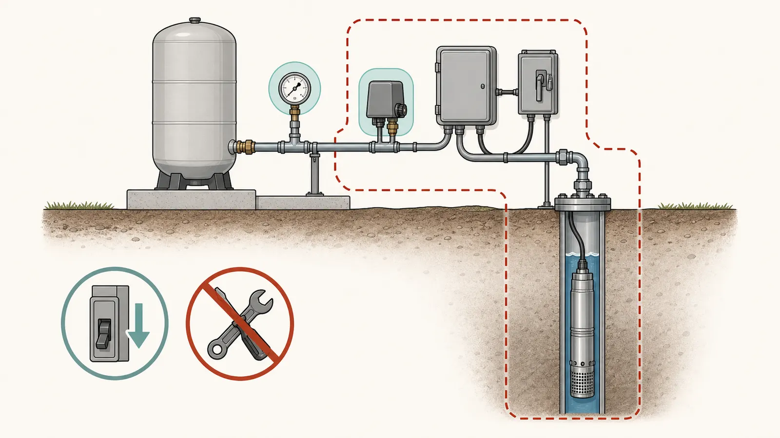
This is a homeowner observation and decision surface, not a live-electrical test. You may read labels and the gauge, listen from a safe location, observe whether pressure rises, and make one reset attempt only when the exact switch label or manual gives a homeowner-directed procedure. Do not open the switch cover, touch contacts, bypass a control, open the well, pull a pump, test live wiring, loosen pressurized fittings, or repeatedly hold a lever to force operation.
1. Start with the distinction that matters
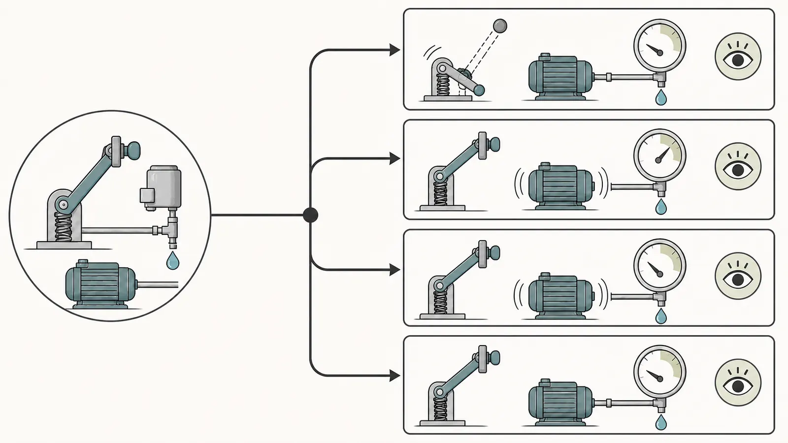
“Only turns on manually” describes several different events. Write down which one you actually see. The difference between “the pump runs only while I hold Start” and “the pump starts after I move the lever to Auto, but will not restart at normal pressure” changes the decision.
| What you observe | What it supports | Safest next action |
|---|---|---|
| Pump runs only while the lever is held; releasing it stops the pump immediately | A maintained low-pressure cutoff may still be active, or the control may not be returning to automatic operation | Stop after the one permitted reset attempt; record pressure and call for service if it drops out again |
| Pump runs with the lever held, pressure rises into the documented automatic range, and it then cycles in Auto | A protective lockout may have cleared, if the switch manual says that is how it works | Leave the cover closed; observe one normal cycle and record the readings |
| Pump runs, but pressure rises slowly or never reaches cut-out | Low-producing well, leak, blocked intake or sensing path, check valve, pump wear, or electrical problem is more likely than a simple reset issue | Stop extended operation and arrange qualified well-pump diagnosis |
| Gauge is already at or above cut-in, but the pump needs the lever to start | A pressure-sensing, switch, gauge, or control fault is possible; a low-pressure cutoff alone is less explanatory | Do not adjust the switch; arrange service |
| Pump does not run even while the exact permitted manual control is held | Power, control, motor, wiring, or pump fault is possible | Do not open the control box; stop and call a qualified professional |
| Water pressure or flow returns briefly, then disappears; air, sand, cloudiness, or unusual pump sound appears | A low-yield or changing water-level condition is possible, but the symptom is not proof by itself | Conserve water, stop repeated restarts, and contact a locally authorized well/pump professional |
The first two rows are the only ones where a manual reset could be a reasonable observation. Even there, the reset belongs to the installed model. Schneider distinguishes the 9013 M4 low-pressure cutoff from the M1 maintained manual cut-out: M4 is intended to open below a low-pressure threshold, while M1 is a maintained Off position used for an extended shutdown. (Schneider's M1-versus-M4 explanation) A lever that looks similar can have a different purpose on another product.
The pressure gauge is a clue, not a laboratory instrument. A reading that does not change may mean the system is not gaining pressure, but it can also reflect a gauge problem or a pressure-sensing problem. Likewise, a pressure increase does not prove that the pump, well, tank, switch, and check valve are all healthy. Your goal is to classify the next safe branch and give a professional a reliable record.
2. Find the switch's safety feature before touching anything
Read the external label, not the inside of the cover
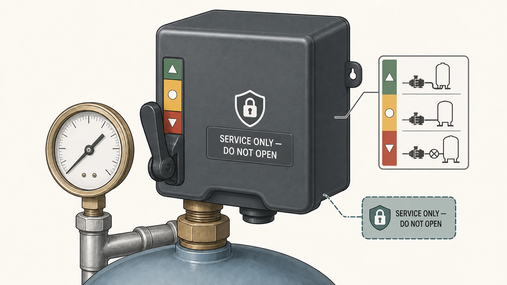
From outside the equipment, record the manufacturer, full model or form marking, pressure range, and every word near the lever. Look for terms such as “low pressure cut-off,” “low pressure cutoff,” “M4,” “Start,” “Run,” “Auto,” “Off,” or “manual reset.” Photograph the label if that can be done without removing a cover or reaching over energized equipment.
Do not infer the switch form from the common 30/50 or 40/60 numbers alone. Pentair's FP217-1140 page describes one specific 30/50 switch with a low-pressure cutoff that shuts pump power off at 20 psi or lower and has a manual reset. That is useful proof that this product category exists, not proof that every 30/50 switch behaves the same way. The page also marks that product discontinued, which is another reason to identify the installed model before buying a replacement. (Pentair's FP217-1140 product information)
On a Schneider 9013 M4, the low-pressure cutoff is fixed at 10 psi below the switch's cut-in setting and follows that setting if the cut-in is changed. Schneider also says the lever must be held against spring pressure to let the system build above the cutoff, then moved to Auto. (Schneider's M4 reset boundary) Do not transfer that 10-psi relationship, lever motion, or reset timing to an unverified switch.
Confirm the system type
This page is aimed at a conventional pressure-switch system: a pump starts and stops at a lower and upper pressure, with a pressure tank supplying water between cycles. If the equipment has a variable-frequency drive, constant-pressure controller, electronic transducer, or a digital control panel that changes motor speed, stop using this decision surface as soon as you identify that system type. Its “manual” control may be a commissioning, service, or fault-recovery function rather than a simple low-pressure lever.
Record the controller and pump model instead. A professional can use the current manual to determine whether the control is protecting against low water, a sensor fault, a motor fault, or a controller fault. Do not create a manual start by jumping wires or pressing a reset that is not described for the model.
Establish the homeowner-safe boundary
Pentair's Simer manual warns of hazardous voltage and says to disconnect power before servicing the pump; it specifically says to disconnect power to the control box before working on or around the control box, pipes, cable, pump, or motor. (Pentair's Simer safety instructions) That is a service boundary, not an invitation to remove the cover after switching off a breaker. A homeowner may not know whether another circuit, a disconnect, stored pressure, or an unexpected restart remains present.
For this page, “safe observation” means:
- Read an external equipment label and the gauge face without opening anything.
- Observe the pump sound and the pressure response from a dry, stable location.
- Use a normal household cold-water fixture only if water is flowing normally and there is no sign of contamination, flooding, or electrical danger.
- Follow one exact manufacturer-directed external lever procedure only when the switch label or manual clearly permits it.
Stop and assign the work to a qualified professional if you would need to open the control, check voltage, clean a pressure port, adjust switch springs, remove a switch from piping, measure tank precharge, open the well, lower or pull the pump, enter a pit, or change a check valve or relief valve.
3. Run one controlled reset and record what happens
The purpose of one reset is not to “make the pump work.” It is to distinguish a documented protective lockout from a system that cannot recover. Make the attempt only when all of these are true:
- The external label or current manual identifies a low-pressure cutoff and gives a reset procedure.
- There is no cracked enclosure, exposed conductor, active leak, flooding, burning smell, smoke, repeated breaker trip, or other immediate hazard.
- You can see the gauge without standing in water or reaching across electrical equipment.
- The home has enough water for the observation, or you have a safe alternative for drinking and sanitation if the system fails to recover.
- You will make one attempt, not a series of restarts.
A model-specific example, not a universal procedure
For the Schneider 9013 M4, Schneider's public instructions say to move the selector to Start and hold it until system pressure rises above the low-pressure cutoff; then release it to Auto. Its troubleshooting manual describes the same boundary as holding Run until pressure is within 10 psi of cut-in. (Schneider's M4 FAQ; Schneider's 9013 troubleshooting guide) Use the wording on the installed product's current instructions if it differs. Do not hold the lever indefinitely while waiting for a pump that cannot build pressure.
If the lever is spring-loaded and must be held, keep your hand at the external control only as the manual directs. Watch the gauge. Record whether the pump starts, whether the needle moves upward, whether the water output changes, and whether the pump stops when you release the lever. Do not touch the contacts, probe the enclosure, or remove the cover to “see what is happening.”
What counts as a stop signal
Release the control and stop the attempt if:
- The gauge does not rise or falls immediately.
- The pump runs continuously without approaching the documented automatic range.
- The pump makes a grinding, rattling, repeated clicking, or unusually loud sound.
- Air, sand, cloudiness, discoloration, or an unusual odor appears at a faucet.
- A breaker, fuse, overload, or controller fault occurs.
- Water leaks, sprays, floods, or reaches electrical equipment.
- The lever, enclosure, gauge, piping, or tank appears damaged.
Cloudy, discolored, sandy, or odorous water is also a water-use stop signal. Treat it as suspect: do not drink it or use it for cooking until the local health authority or a locally authorized well-water professional gives guidance. Use bottled water or another safe alternate supply for drinking, cooking, food preparation, and other uses where water may be swallowed. CDC guidance gives the same safe-source and local-health-department boundary when private-well contamination is suspected. (CDC well-water treatment guidance)
Pentair's pump manual lists low water level, low voltage, plugged intake screen, a stuck check valve, and worn impellers or diffusers among possible causes of little or no delivered water. It also warns that running a pump while airlocked can cause loss of prime and serious damage. (Pentair's Simer troubleshooting guide) Those branches require service-level diagnosis; they are not reasons to keep the lever held.
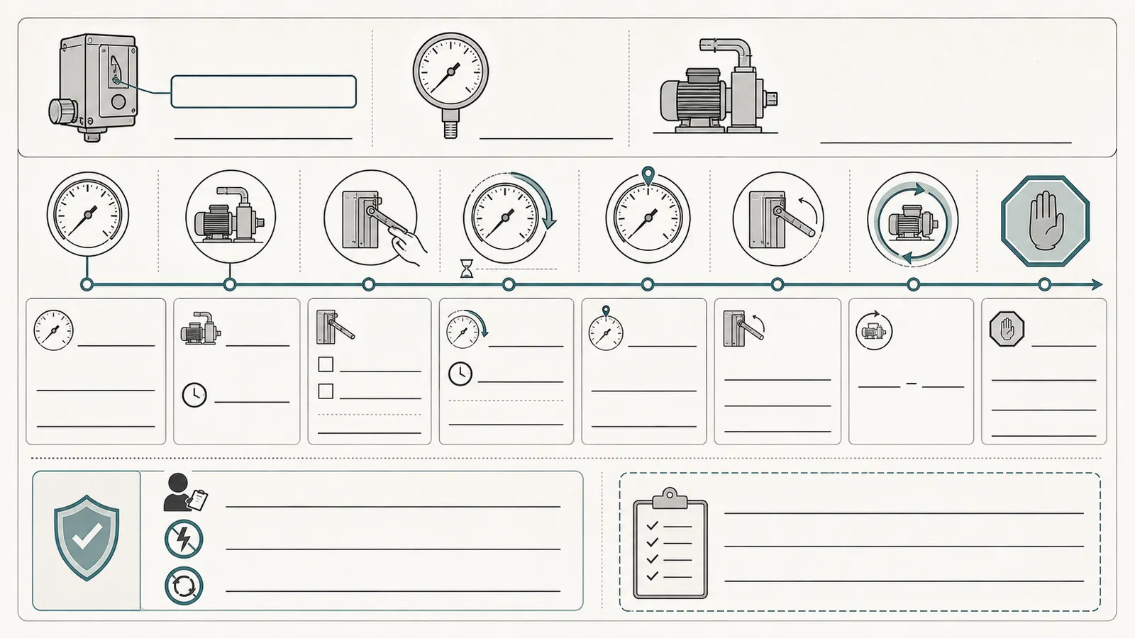
The pressure-and-timing log
Use one line for the reset attempt. Write what you observed, not what you think the part is doing.
| Field | Record |
|---|---|
| Date and time | ______________________________ |
| Switch manufacturer and full model/form | ______________________________ |
| External lever words or low-pressure label | ______________________________ |
| Pump type/controller, if labeled | ______________________________ |
| Gauge pressure before attempt | __________ psi |
| Does the pump start when the permitted control is used? | yes / no / uncertain |
| Does the pump run only while the lever is held? | yes / no / uncertain |
| Time from start to first visible pressure movement | __________ seconds / no movement |
| Highest observed pressure during the permitted attempt | __________ psi / unknown |
| Water output or faucet behavior | ______________________________ |
| Pump sound | normal / changed / loud / clicking / unknown |
| Result when control is released or returned to Auto | ______________________________ |
| Did it reach the documented automatic range? | yes / no / unknown |
| Stop reason | ______________________________ |
Do not fill in a pressure value from a remembered “normal.” Use the installed gauge reading. If the gauge is unreadable, damaged, or obviously inconsistent with the home's water behavior, record “gauge uncertain” and stop; do not remove it or loosen its connection.
4. Read the pressure-and-time pattern
The useful question is not simply “did it start?” It is “what did pressure do while the pump was allowed to run under the exact model procedure, and what happened when the procedure ended?”
Pattern A: confirmed Schneider 9013 M4, pressure below cut-in, and dropout again within 10 psi of cut-in after release
This is the narrow Schneider 9013 branch—not a conclusion for every switch with a lever. Schneider's 9013 guide says that when pressure is below cut-in and a confirmed M4 cuts out again within 10 psi of cut-in after the lever is released, the water source is low; it also says not to actuate the lever again until the source has recharged. (Schneider's low-source troubleshooting branch)
Treat “source is low” as a bounded manufacturer troubleshooting conclusion, not a permanent diagnosis. USGS explains that a well is considered dry when the water level drops below the pump intake and that water levels may recover as recharge increases. Depth, aquifer type, pumping, and recharge all matter. (USGS explanation of well drawdown) A seasonal or drought-related drawdown can therefore look like a failed pump or switch at the tank.
The next safe action is to stop restarting, reduce water use, and contact a locally authorized well/pump professional. Preserve the log. Do not open the well cap to look for water, lower the pump, throttle a valve, or run the pump “just a little longer” unless a qualified professional directs that work for the installed system.
Pattern B: pressure rises into the automatic range and the system remains in Auto
If the confirmed model's instructions say to return the lever to Auto after recovery, and the pump then stops at its normal upper pressure and later restarts automatically, the original event is consistent with a protective lockout that cleared. It does not prove that the well has adequate long-term yield or that the switch is healthy.
Observe at most one normal cycle without touching the control. Record the cut-in and cut-out readings if they are visible from the gauge and the pump stops and restarts on its own. If the pump takes much longer than usual to reach cut-out, the pressure falls quickly while no fixture is open, or the symptom returns, move to service rather than repeating the reset.
Reduced yield can be intermittent rather than permanent. USGS explains that water can fall below a pump intake and later return as recharge increases, with well depth, aquifer type, pumping, and recharge affecting the result. (USGS explanation of well drawdown) A symptom that improves after a water-use pause is therefore compatible with drawdown, but it is not proof of a dry well or a healthy pump. Use a locally authorized well/pump professional for unresolved recovery problems, and check local requirements before any well, electrical, or pump work. A successful single reset is still only a recovery observation, not a clean bill of health.
Pattern C: pressure rises, but the switch does not return to automatic operation
If the gauge reaches or passes the model's stated low-pressure recovery point but the pump still stops as soon as you release the lever, or will not operate in Auto, do not hold the lever again. The lockout may not be clearing, the lever may be a different form, the gauge may not reflect pressure at the switch, or the switch's sensing path or contacts may have a fault.
Schneider's troubleshooting table includes a defective switch, an obstructed diaphragm entry, a check-valve issue, and an inaccurate gauge or pressure reading among possible causes in this area. Its corrective column assigns switch removal, pressure-port inspection, contact work, and related checks to qualified service personnel. (Schneider's 9013 qualified-service troubleshooting) That is exactly the point where a homeowner should give the professional the model, gauge behavior, reset result, and timing log—not clean the port or replace the switch based on a guess.
Pattern D: pressure is already at or above cut-in, but the pump will not start automatically
A low-pressure cutoff is a poor explanation when the gauge is already at or above the ordinary cut-in pressure and the pump still requires manual intervention. Possible branches include a pressure-sensing problem, inaccurate gauge, mechanical switch fault, wiring or control fault, or a pump that is not responding to the automatic command. The pattern does not tell you which one.
Do not adjust the pressure springs, bridge the contacts, move wires, or substitute a switch. Ask the professional to verify the gauge against the switch pressure, the switch form, the sensing connection, the control circuit, and the pump's response using an appropriate de-energized and qualified procedure. The purpose of your observation is to prevent a low-pressure-cutoff assumption from hiding an ordinary control fault.
Pattern E: the pump runs but cannot build pressure
This is not a reset success. A pump that runs while held but never approaches the automatic range may be moving too little water or may be losing pressure somewhere. The distinction between “pump runs” and “system can build pressure” is central.
Possible branches supported by the Simer manual include a low water level, low voltage, a plugged intake screen, a stuck check valve, or worn impellers and diffusers. (Pentair's list of little-or-no-water causes) A leak, open fixture, failed tank or plumbing component, or pressure-sensing problem may also be relevant depending on the installation. The observation cannot separate these by itself.
Stop extended operation. A pump that cannot build pressure may be running under a low-water or air-entry condition, and repeated attempts add heat, wear, and risk without improving the diagnosis. A professional may need the well record, pump curve, static and pumping water levels, electrical measurements, flow measurement, and a controlled inspection. Those are not homeowner tests in this decision surface.
5. Separate the likely branches without opening the system
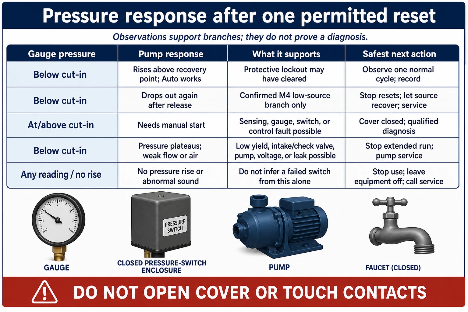
The table below is a service-handoff matrix. “More likely” means the observation changes the order of questions; it does not identify a failed part.
| Observed combination | What it makes more likely | What it does not prove | Next action |
|---|---|---|---|
| Confirmed Schneider 9013 M4; gauge below cut-in; after release it drops out again within 10 psi of cut-in | The documented M4 low-source branch or inadequate pressure recovery | It does not prove the well is permanently dry, and it does not apply to an unverified switch | Stop resetting; let the source recover only if the manual allows; call a well professional if unresolved |
| Confirmed Schneider 9013 M4; pressure rises above the documented recovery point; Auto works for one normal cycle | Protective trip cleared | It does not prove adequate well yield, correct gauge accuracy, or a healthy switch | Record one cycle and monitor; service if slow, intermittent, or recurrent |
| No low-pressure label or model cannot be identified; lever behavior is unclear | Wrong-form assumption or ordinary switch/control fault | It does not prove the switch is bad | Stop manipulating; send clear label photos and log to a professional |
| Gauge at/above cut-in; pump needs manual start | Sensing, switch, gauge, control, or wiring fault | It does not prove contacts are burned or port is clogged | No cover removal; qualified diagnosis |
| Pump runs but pressure plateaus below cut-out; water output is weak or air enters | Low well yield, intake/check-valve/pump problem, low voltage, or a leak | It does not prove a pump replacement is needed | Stop extended run; locally authorized well/pump service |
| Pump will not run with permitted external start; breaker or overload changes state | Electrical, control, motor, or pump fault | It does not prove a pressure-switch fault | Leave equipment off; locally authorized electrician or pump professional |
| Pressure recovers only after long water-use pause; symptoms follow drought or heavy use | Temporary drawdown or reduced well yield | It does not prove a permanent well failure | Conserve water and obtain well-specific testing |
Low-producing well versus pressure-sensing fault
A low-producing well is one possible explanation when the log shows weak pressure recovery, longer pumping, pressure loss after demand, or improvement after a rest period. USGS explains that water can fall below a pump intake and later recover as recharge increases, but that relationship cannot diagnose your property from a gauge reading alone. (USGS explanation of well drawdown) Treat air, sediment, cloudy water, or unusual flow as additional service clues and water-use stop signals—not as proof of a particular well condition.
A pressure-sensing fault is more plausible when the gauge shows pressure in the expected range but the pump does not change state as the automatic control should, or when the gauge and pump behavior disagree. A blocked sensing port, defective diaphragm or switch, bad gauge, check-valve condition, or control fault can create that mismatch. Schneider lists these as service branches for its 9013 family. Do not turn that reasoning into a DIY port-cleaning procedure: the pressure switch is connected to the pressurized system and may be associated with energized contacts.
Keep fixture-only symptoms separate
If only one fixture is weak while the gauge and pump follow the expected cycle, record that as a separate symptom rather than diagnosing the pump from it. This page does not establish whether a local plumbing problem exists. Do not open a filter housing or piping under pressure; have a locally authorized plumbing or well/pump professional evaluate the separate flow complaint.
6. What not to do and when to stop
Do not open the pressure switch or control box
The switch can contain energized line voltage even when the pump is not running. Do not inspect contacts, tighten terminals, test voltage, bypass the switch, install a jumper, or hold contacts closed. Pentair's manual explicitly places the control box, wiring, pump, and motor behind a power-disconnection and service boundary. Qualified electrical work must follow the installed equipment instructions and applicable local requirements.
Do not repeatedly hold the lever
The manual lever is not a pump-control substitute. Repeatedly forcing a low-pressure-cutoff switch can keep a pump running when the source is not recovering. Schneider's 9013 guide specifically says not to actuate the M4 lever again until the source has recharged. If the pump cannot build pressure, the next useful action is a service call and a water-use reduction—not a longer hold.
Do not assume the switch is the failed part
Replacing the switch before identifying the form can remove a protection feature, install the wrong pressure range, or leave a low-yield well and failing pump undiscovered. A different-looking replacement can also have different contacts, connection, pressure rating, or reset behavior. Give the professional the exact model and photographs of the external label.
Do not open the well or pull the pump
The well opening can be a contamination, fall, electrical, and equipment hazard. Pump removal involves heavy equipment, drop pipe, cable, water pressure, and the risk of damaging the well or pump. Low water level is diagnosed from well records, pumping conditions, and qualified measurements—not by leaning over the casing or lowering an improvised line.
Do not keep running a pump that cannot build pressure
If pressure does not rise, rises only weakly, falls immediately, or the pump becomes noisy, leave the system off as directed by the equipment manual and arrange service. If the home needs water for drinking, cooking, medical care, or sanitation, use a safe alternate supply. If water is cloudy, discolored, sandy, or has an unusual odor, treat it as suspect: do not drink it or use it for cooking until the local health authority or a qualified well-water professional gives guidance. Use bottled water or another safe alternate supply for drinking, cooking, food preparation, and other uses where water may be swallowed. CDC guidance likewise directs people who suspect private-well contamination to use bottled water or another safe source and contact the local health department. (CDC well-water treatment guidance) Do not assume the reset caused or cured a water-quality problem.
7. Hand off a useful service record
The best outcome of this page is not a guessed part. It is a concise record that lets a well-pump professional separate protective lockout, low source, pressure sensing, electrical, and pump branches without making you repeat unsafe actions.
Send or bring:
- The switch manufacturer, full model/form, pressure range, and a clear external-label photograph.
- The pump manufacturer and model, motor voltage if labeled externally, and whether a control box or variable-speed controller is present.
- Pressure-tank manufacturer/model if visible without opening or disconnecting anything.
- Gauge pressure before the attempt, first pressure movement, highest observed pressure, and whether the pump reached automatic operation.
- Whether the lever had to be held, whether it was spring-loaded, and what happened immediately on release.
- The elapsed time of the attempt and whether the pump sound, water clarity, air, sand, or flow changed.
- Any recent drought, heavy household use, plumbing work, filter change, outage, breaker event, or pressure symptom.
- The well completion report, pump-setting depth, prior service records, and any record of seasonal recovery if available.
Ask the professional to answer these bounded questions:
- Is this exact switch equipped with a low-pressure cutoff, and what is its documented reset procedure?
- Does the observed pressure-and-release pattern support a low water source, or does it point toward sensing, gauge, control, or pump service?
- Can the well's static and pumping water levels and recovery be evaluated without repeated dry running?
- Can flow and pressure be checked at the relevant operating point rather than inferred from motor horsepower?
- Are the tank, gauge, check valve, sensing port, relief protection, pump, and electrical controls compatible and serviceable as a system?
The decision boundary is simple: one documented, model-permitted reset can classify an observed lockout; it cannot certify the well, pump, pressure switch, tank, wiring, or water quality. If the pump does not recover to automatic operation, if it drops out again, or if it cannot build pressure, leave the lever alone and hand off the record.
Sources and scope
Evidence behind this page
- Schneider Electric — Video: How does the M4 option on a 9013 F Pressure switch work?
Schneider 9013F pressure switches with the M4 option. The reset behavior and 10-psi relationship are not universal instructions for every pressure switch.
- Schneider Electric — 9013: What is the difference between M1 and M4 options?
Schneider 9013 pressure-switch form options sold in North America; it does not identify the form of an unmarked or different-brand switch.
- Schneider Electric — Preventive Maintenance and Troubleshooting Guidelines for Class 9013F and 9013G Pressure Switches
Schneider's 9013F/9013G troubleshooting table; the low-source inference is model-specific and is not a field proof that every well is dry.
- Schneider Electric — Preventive Maintenance and Troubleshooting Guidelines for Class 9013F and 9013G Pressure Switches
Schneider's troubleshooting table for the referenced pressure-switch families. Port cleaning, switch removal, contact work, and wiring checks are not homeowner instructions.
- Pentair Parts2O — FP217-1140 30/50 PSI with Low Pressure Cut-Off Pressure Switch
The discontinued Pentair Parts2O FP217-1140 product page; its 20-psi cutoff and manual-reset description apply to that product, not to every 30/50 switch.
- Pentair Simer — 2- and 3-Wire Submersible Pumps Installation and Operating Manual
Pentair Simer submersible-pump installation and operating instructions; the page uses this as a conservative safety boundary and does not present it as a complete electrical code.
- Pentair Simer — 2- and 3-Wire Submersible Pumps Installation and Operating Manual
Pentair Simer pump troubleshooting for the referenced pump families. The listed causes are diagnostic possibilities, not a homeowner authorization to pull a pump or test live voltage.
- U.S. Geological Survey — What determines if a well will go dry?
USGS general groundwater explanation; it supports the distinction between a low-water condition and a permanently failed well but does not diagnose an individual property.
- Schneider Electric — Preventive Maintenance and Troubleshooting Guidelines for Class 9013F and 9013G Pressure Switches
The qualified-service column of Schneider's 9013 troubleshooting table; it does not provide a homeowner procedure for opening or rewiring the switch.
- CDC — Guidelines for Treating Well Water
CDC guidance for suspected or confirmed harmful germs or chemicals in private-well water. A visual or odor change is a stop signal for this article, not proof of a particular contaminant.