How to Tell If Your Submersible Well Pump Is 2-Wire or 3-Wire
A homeowner-safe worksheet for identifying a 2-wire or 3-wire submersible well pump from labels, records, and a control box before buying parts or approving a pump pull.
The short answer
Start with the pump or control-box model record, not a wire count. A 3-wire submersible motor normally has a dedicated above-ground control box; a 2-wire motor normally does not. The motor-wire names exclude the equipment-grounding conductor, and a pressure switch is not the same as a motor control box. Verify the exact model, voltage, horsepower, and wiring diagram before buying a box. Do not open energized controls, test live wiring, open the well, or pull the pump.How to Tell If Your Submersible Well Pump Is 2-Wire or 3-Wire
Start with the model record or the exterior label on a pump control box—not with a wire count. A 3-wire submersible motor normally uses a dedicated above-ground control box; a 2-wire motor normally does not. In this naming convention, “2-wire” and “3-wire” describe the motor conductors and exclude the equipment-grounding conductor. A pressure switch near the tank is not the same thing as a motor control box. Verify the exact pump or motor model, control-box model if present, voltage, horsepower, and manufacturer wiring diagram before buying a replacement part.
This page is for safe observation and documentation. Do not remove an electrical cover, open an energized control box, test live wiring, change pressure-switch settings, manipulate a pressurized tank or fitting, open a well, enter a confined space, lift equipment by its cable, or pull a pump. Zoeller’s current installation instructions say electrical circuit and hardware checking should be performed by a qualified and licensed electrician, and warn that 3-wire motors operated without the correct control box can fail. (Zoeller’s 2026 submersible-pump instructions)
1. Use the identification rule before you inspect anything
The practical answer is a confidence ladder:
- Best evidence: an installation record, pump schedule, service invoice, or manufacturer manual that names the motor configuration.
- Strong visible evidence: an exterior label on a dedicated pump motor control box that identifies the box as a 3-wire submersible-pump control box, with a compatible pump or motor model.
- Supporting evidence: the pump or motor model and the manual’s wiring diagram.
- Weak evidence: the appearance of a pressure switch, the number of wires someone remembers seeing, or a guess based on pump age.
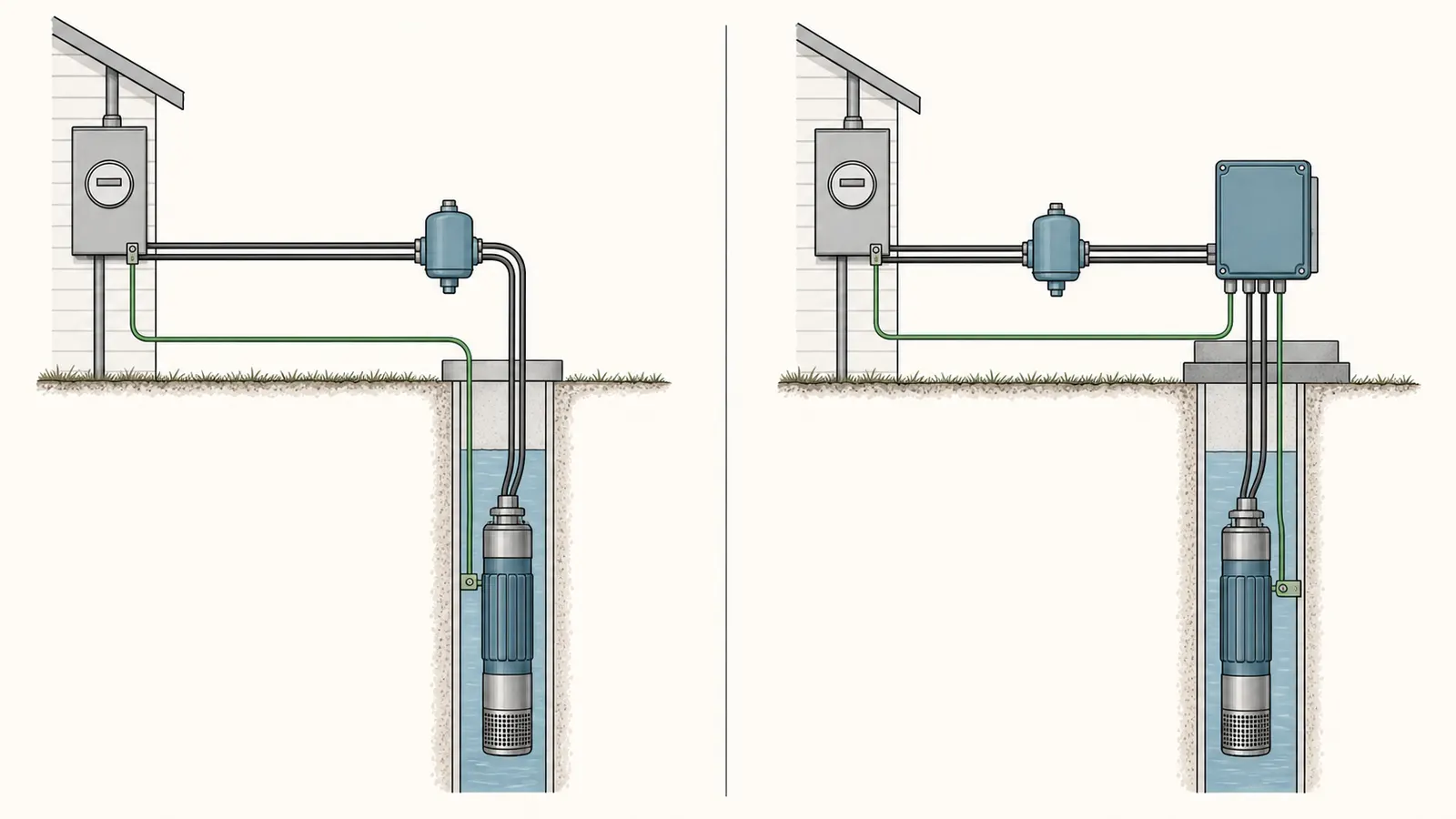
Red Lion’s homeowner product guide defines its submersible pumps as 2-wire or 3-wire models “not including the ground wire.” It describes the 2-wire arrangement as wired directly to the power source and the 3-wire arrangement as wired through a control box. (Red Lion’s submersible-pump product guide) Zoeller’s installation instructions make the same architecture distinction for its four-inch submersible pumps: 3-wire motors require a control box, while 2-wire motors do not. (Zoeller’s motor and control-box guidance)
That does not mean “I see a box, therefore I can order any box.” It means the box is a useful clue that must be matched to the installed motor. A box can be mislabeled, reused, installed for a different controller, or associated with a system whose pump has already been changed. Conversely, a 2-wire pump can still have a pressure switch, disconnect, protection device, junction box, or other above-ground equipment. The presence of above-ground electrical equipment alone does not identify the motor configuration.
The naming trap is important. The equipment-grounding conductor is part of the safety path but is not what turns a motor from “2-wire” into “3-wire.” Zoeller’s wiring instructions show a separate ground wire for the motor connection and explain that grounding protects against shock when exposed metal becomes connected to an electrical circuit. (Zoeller’s grounding and wiring instructions) Do not count conductors yourself, especially not inside a control box or junction box. A visible green or bare conductor is not evidence that the pump is a 3-wire motor, and the absence of a visible conductor is not evidence that grounding is missing.
What you should be able to say at the end
Your goal is not merely “2” or “3.” Record one of these outcomes:
| Outcome | What it means | What you may do next |
|---|---|---|
| Verified 3-wire | A reliable record or matching manufacturer documentation identifies a 3-wire motor, usually with a dedicated motor control box | Ask a qualified well or electrical professional to verify the box and motor match before any part is ordered |
| Verified 2-wire | A reliable record or matching manufacturer documentation identifies a 2-wire motor with no motor control box required by that design | Ask for a diagnosis of the actual failed component; do not buy a 3-wire box as a substitute |
| Probable, not verified | A visible box or system layout suggests one arrangement, but the model or manual is missing | Photograph exterior labels from a safe location and request professional verification |
| Unknown | Records conflict, labels are unreadable, or equipment has been replaced | Treat the configuration as unknown; do not authorize a control-box purchase or pump pull based on a guess |
2. Collect safe visible evidence in the right order
You can usually gather useful information without touching electrical equipment or the well. Work only in a dry, well-lit area where you can stand clear of exposed equipment. If the area is wet, flooded, damaged, or smells of burning insulation, stop and call a qualified professional. EPA specifically warns private-well owners to stay away from a flooded well pump because of electric-shock risk and to get qualified assistance before cleaning, disinfecting, and restarting the system. (EPA private-well protection guidance)
A. Look for paperwork first
Search for the information that often survives when a pump is below grade:
- the original pump or motor invoice;
- a well completion or pump-installation record;
- a service invoice that names the pump and control box;
- a photograph taken during an earlier repair;
- an equipment schedule from a home purchase or inspection file;
- the owner’s manual or installation instructions;
- a warranty registration or product label photograph; and
- a written estimate that identifies the current equipment rather than only the proposed replacement.
Write down the exact characters. “Goulds 1 HP” is not an exact model. Record every letter, number, suffix, voltage marking, and date code that appears in a document. If a document says only “submersible pump,” label it as incomplete rather than filling in the missing configuration from memory.
EPA recommends that private-well owners keep accurate records of well maintenance, including disinfection or sediment removal that may involve chemicals in the well. A service history is therefore useful not only for this identification question but also for future water-safety decisions. (EPA guidance on private-well records)
B. Photograph exterior labels without opening anything
If there is a rectangular or otherwise dedicated control enclosure near the pressure tank, photograph its exterior label from a safe position. Capture:
- manufacturer name;
- control-box model or catalog number;
- voltage marking;
- horsepower range, if printed;
- any “3-wire,” “submersible motor control,” or equivalent wording;
- warning labels; and
- the relationship of the box to the pressure tank and pressure switch.
Do not remove the lid to make the label clearer. Do not pull a disconnect, move a breaker, touch a reset button, loosen conduit, or trace conductors. A professional can identify the internal wiring safely and can decide whether power isolation and testing are required.
C. Photograph the context, not the conductors
Take a wide photograph showing the tank, pressure gauge, pressure switch, control-box exterior, disconnect enclosure, and nearby piping. Take a second photograph of each exterior label. Avoid photographing through an opening or reaching behind equipment. The context can help a professional distinguish a motor-control box from a pressure-switch cover or a well-water treatment controller.
The Water Systems Council explains that a pressure switch starts and stops a pump at preset system pressures and is used on both submersible and jet-pump systems. Its location near the tank and its pressure markings therefore do not, by themselves, identify whether the submersible motor is 2-wire or 3-wire. (Water Systems Council pressure-switch information sheet)
D. Record symptoms separately from identification
Do not let the current symptom contaminate the equipment record. Note whether the home has no water, low pressure, rapid cycling, a tripped breaker, a humming sound, a control alarm, an intermittent start, visible leaking, or a recent power event—but do not convert the symptom into a diagnosis.
Zoeller’s troubleshooting chart lists several possible causes for a motor that does not start, including a blown fuse or tripped breaker, inadequate power, a faulty pressure switch, faulty cable or motor, faulty control-box parts, loose connections, and a bound pump. It also lists multiple possible causes for frequent starting or continuous running. (Zoeller troubleshooting chart) The configuration question narrows what parts could be compatible; it does not identify the failed part.
3. Tell the pressure switch from the motor control box
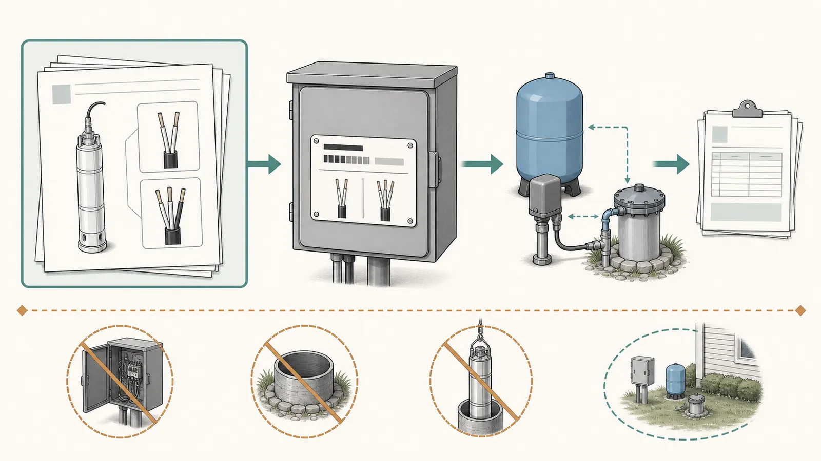
This is the most common visual mistake. A conventional well system may have a pressure switch mounted at or near the tank cross, plus a separate control box elsewhere. Some systems may have no separate motor control box. A pressure switch controls when the pump starts and stops based on water-system pressure; a 3-wire motor control box handles motor-starting components and the motor connection.
The two enclosures may be close together, and a pressure switch can itself look like a small electrical box. Do not classify the system from size, shape, color, or location. Use the label and the manual.
| Visible item | What it can tell you | What it cannot tell you |
|---|---|---|
| Pressure switch near the tank | The system uses pressure-based pump control, or a similar pressure-control arrangement | Whether the motor is 2-wire or 3-wire |
| Dedicated box labeled for a 3-wire submersible motor | Strong evidence of a 3-wire architecture | Whether the box matches the installed motor or is currently functional |
| Pressure gauge | A place to observe system pressure if safely accessible | Motor configuration, horsepower, voltage, or pump condition |
| Disconnect or breaker enclosure | That the system has an electrical supply isolation point | The number of motor conductors or the correct replacement part |
| Treatment controller or booster controller | That another water device is present | That it is the submersible motor’s control box |
| No visible control box | Supports—but does not prove—a 2-wire arrangement | Whether a box is hidden, integrated, removed, or unrelated to the pump |
The distinction matters because a pressure-switch replacement is not a substitute for a 3-wire motor control box. The Water Systems Council says pressure-switch selection depends on cut-in and cut-out pressure, tank precharge, and connection size, among other details. It also cautions that improper adjustments can damage the system or injure someone and says electrical equipment should be serviced by qualified electrical maintenance personnel. (Water Systems Council pressure-switch safety and selection guidance)
Do not remove a pressure-switch cover to see what is inside. Do not adjust the nuts or electronic settings. A pressure reading visible on a gauge can be recorded as an observation if the gauge and surrounding area are dry and intact, but the reading does not identify the motor configuration.
4. Verify the model, voltage, and horsepower before buying anything
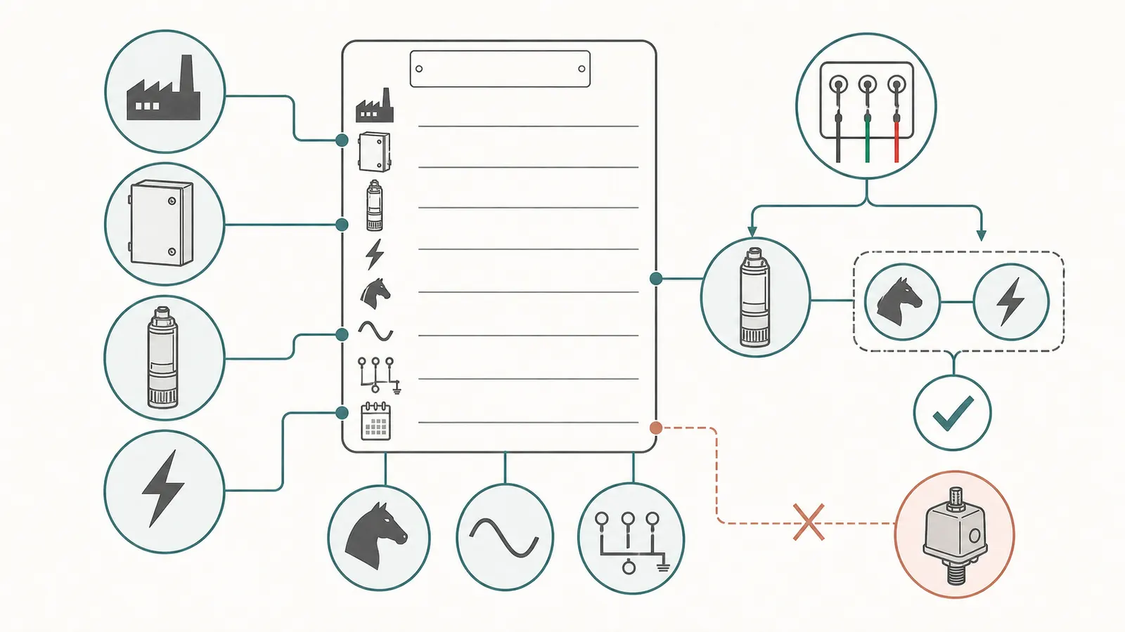
Once you have a possible 2-wire or 3-wire result, build an identity card. The minimum fields are:
| Compatibility field | Your record | Why the professional needs it |
|---|---|---|
| Pump or motor manufacturer | __________ | Product families use different controls and diagrams |
| Exact pump or motor model | __________ | “1 HP submersible” is not a unique part identity |
| Motor configuration | 2-wire / 3-wire / unknown | Determines whether a separate motor control box is part of the design |
| Control-box manufacturer and model | __________ / __________ | A box must be checked against the installed motor, not just the symptom |
| Voltage | __________ | Zoeller specifies matching the control box to the motor’s voltage rating |
| Horsepower | __________ | Zoeller specifies matching the control box to the motor’s horsepower rating |
| Phase or controller type, if documented | __________ | Helps avoid mixing single-phase, three-phase, or variable-speed equipment |
| Wiring diagram or manual | link / file / unknown | The installed manufacturer’s diagram controls the interpretation |
| Well and pump records | __________ | Depth, pump setting, and previous repairs can affect the repair scope |
Zoeller’s current instructions are explicit: a 3-wire motor needs a control box sized to the same horsepower and voltage rating as the motor, while a 2-wire motor does not require a control box. They also say operation of a single-phase 3-wire motor without a control box or with an incorrect box can result in motor failure and void the warranty. (Zoeller control-box compatibility instructions)
Treat that as a compatibility gate, not a shopping shortcut. A box that is the same brand, same voltage, or same horsepower but not the correct model may still be wrong. A replacement pump may also be a different architecture from the pump it replaces. Ask the professional or supplier to confirm the complete motor-and-control-box pairing in writing.
Xylem’s Goulds Water Technology PumpSaver instructions show the same architecture distinction in separate diagrams: one for a standard 3-wire control box and one for a 2-wire pump direct-feed arrangement. The document also identifies a protection device that can serve 230-volt, 2- or 3-wire, single-phase pumps in a stated horsepower range. That illustrates why an accessory’s label or range is not enough to identify the installed pump. (Xylem/Goulds wiring diagrams)
Questions to ask before a part is ordered
Send the professional or supplier the exterior photos and ask:
- Does the documentation identify the existing motor as 2-wire or 3-wire?
- Is the visible box a motor control box, a pressure switch, a pump-protection device, or another controller?
- What exact pump or motor model is the proposed part compatible with?
- What voltage and horsepower are being matched?
- Is the proposed work limited to the accessible control box, or does it assume cable, motor, pump, wellhead, or drop-pipe work below grade?
- What evidence supports the proposed failure?
- What startup or operational check is included after the repair?
- If the configuration cannot be verified from records, what professional inspection is required, and what is explicitly excluded?
If the answer to the first three questions is “unknown,” do not use a generic online part listing as the missing evidence.
5. Map the result to the right repair scope
A verified configuration changes the list of compatible parts. It does not decide whether the next job is a control-box repair, a different above-ground repair, a diagnostic visit, or a pump pull.
Verified 3-wire: investigate the box first, not automatically the pump
On the cited Red Lion design, the external control box contains electronics that can be replaced without pulling the pump when the box is the faulty component. Red Lion contrasts that with its cited 2-wire design, where electronics are located inside the pump and a failed electronic component may require pump replacement. (Red Lion’s control-box service explanation)
Use that as a decision branch, not as a diagnosis. A 3-wire result makes an above-ground control-box diagnosis plausible. It does not prove the control box is bad. Zoeller lists faulty power, pressure switch, cable, motor, connections, pump binding, and other causes alongside faulty control-box parts. A professional may need to establish which branch is supported before recommending a pump pull.
Ask for a quote that names the accessible component, the exact replacement model, the matching voltage and horsepower, the startup check, the warranty, and the conditions that would trigger a pump-pull change order.
Verified 2-wire: do not buy a 3-wire box as a workaround
A 2-wire motor normally does not use the separate motor control box described for a 3-wire motor. If the system has no such box, the failure may instead involve the pressure switch, power supply, cable, motor, pump, tank, check valve, piping, or well conditions. The correct next step is diagnosis within the installed design.
Do not infer that “no control box” means “the pump has failed.” A pressure switch can fail; a well can have a low-water condition; a leak or check valve can affect pressure; and a cable or motor fault may require professional electrical testing. A 2-wire result narrows the compatible architecture, not the root cause.
Unknown or conflicting: pause the purchase decision
If the exterior box says one thing but the service record names another pump, or if the model is unreadable, write “configuration not verified.” Give the professional all evidence and ask for a written identification. If the proposed part depends on a model number that nobody has confirmed, a diagnostic visit is a clearer scope than a speculative replacement.
Pump pull: a different authorization
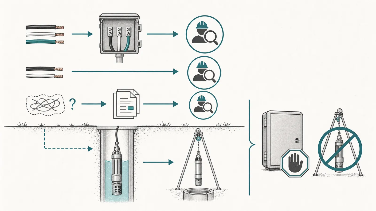
A pump pull means accessing below-grade equipment. It may be appropriate if the motor, pump, cable, splice, drop pipe, or well-side component is implicated. It is not automatically justified because the pump is 2-wire, because a box label is missing, or because water pressure is low.
Before authorizing a pull, ask the professional to state:
- what observation or qualified test makes below-grade access necessary;
- whether the scope is removal and inspection, repair, replacement, or all three;
- what pump, motor, cable, drop pipe, check valve, pitless adapter, well seal, or fittings are assumed reusable;
- what happens if the assembly is stuck, damaged, contaminated, or a different model than expected;
- how additional labor, equipment, depth, travel, disposal, and materials will be priced;
- how the pump will be reinstalled and the system started safely; and
- what pressure, flow, leak, and water-quality follow-up is included or excluded.
Do not open the well, handle the drop pipe, or help lift the pump. EPA advises hiring a certified well driller for new construction, modification, or abandonment and closure; exact licensing and permitting requirements vary by state and locality. (EPA private-well protection guidance)
6. Complete the homeowner worksheet without making a hazardous measurement
Use this record before requesting a replacement part or comparing quotes. “Not visible” and “unknown” are valid entries.
| Field | Safely observed or documented | Interpretation | Confidence / next question |
|---|---|---|---|
| Dedicated motor control box visible? | yes / no / not sure | A labeled 3-wire box is a strong clue; no box is not proof | __________ |
| Exterior box label | __________ | Is it explicitly for a 3-wire submersible motor? | __________ |
| Pump/motor model record | __________ | Does the manufacturer manual state 2-wire or 3-wire? | __________ |
| Control-box model | __________ | Does the manual list the motor model, voltage, and HP? | __________ |
| Voltage on record | __________ | Do the pump and box ratings match? | __________ |
| Horsepower on record | __________ | Do the pump and box ratings match? | __________ |
| Pressure switch present | yes / no / not sure | Pressure control is separate from motor configuration | __________ |
| Recent service or replacement | __________ | Could the current equipment differ from the original? | __________ |
| Current symptom and timing | __________ | Symptom is not the same as failure confirmation | __________ |
| Water event or flood | yes / no / unknown | Stop and use qualified flood-response help if affected | __________ |
| Proposed repair | __________ | Above-ground repair, diagnosis, or pump pull? | __________ |
| Evidence attached to quote | __________ | What test or observation supports the scope? | __________ |
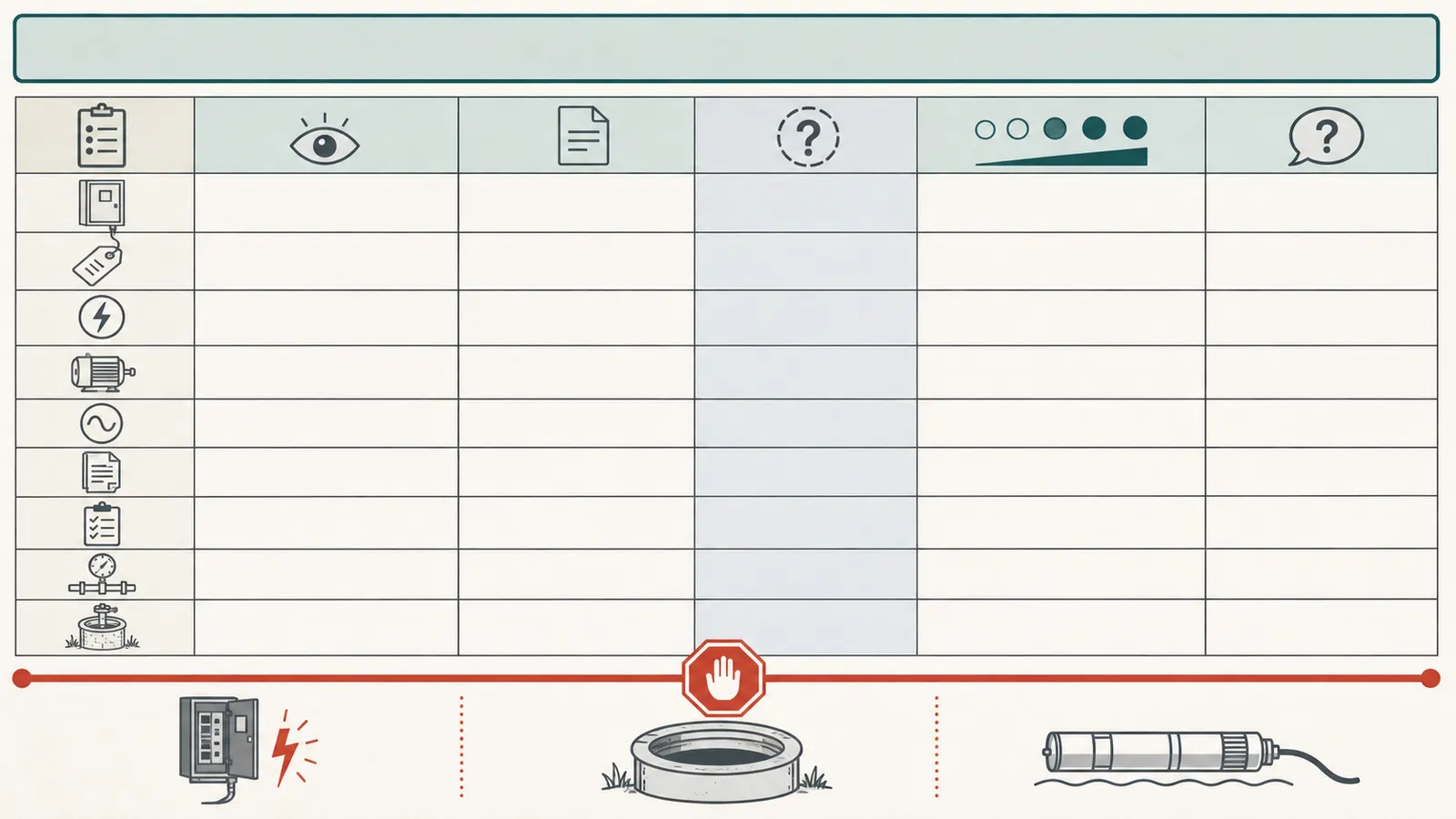
Use three labels in your notes:
- Observed: visible label, intact enclosure, pressure shown on an accessible gauge, or symptom you directly noticed.
- Documented: model, voltage, horsepower, and configuration stated in a manufacturer manual, invoice, installation record, or professional report.
- Inferred: a conclusion such as “probably 3-wire because there is a box.”
Only the first two categories should drive a part-compatibility decision. An inference can guide the next question but should not authorize a purchase or a pump pull.
Safe pressure notes are still not a wire test
If an intact pressure gauge is visible from a dry, safe location, you may record what it displays and when. Do not remove a cover, connect test leads, adjust the switch, loosen a fitting, open the tank air valve, or deliberately run the pump to create a reading. The Water Systems Council says pressure-switch adjustments belong to a licensed well contractor and warns that improper adjustments can cause mechanical damage or personal injury. (Water Systems Council pressure-switch caution)
Do not use a pressure number to infer horsepower, voltage, or wire configuration. A pressure reading describes one operating condition of the water system. It does not identify the motor architecture.
7. Hand off a clear record and stop before electrical or well work
Give the professional a compact packet:
- The exact homeowner symptom, including when it began and whether it is constant or intermittent.
- Exterior photographs of the tank area, pressure switch, control-box label, disconnect enclosure, wellhead area, and model records—only from safe locations.
- The pump, motor, and control-box model numbers exactly as written.
- The recorded voltage and horsepower, with “unknown” where no reliable record exists.
- The installation date, prior repairs, pump replacement history, and any flood, power, sediment, odor, taste, or color event.
- Your worksheet showing what is observed, documented, inferred, and still unknown.
- A request for the proposed diagnosis, evidence, compatible part number, repair boundary, startup check, warranty, exclusions, and change-order rule.
The handoff should produce a written sentence such as: “The existing motor is identified from [record/manual] as a 3-wire, [voltage], [horsepower] model; the visible box is [model]; the proposed box is compatible according to [manufacturer document]; below-grade access is not included unless [specified finding].” Or: “The configuration remains unknown; no part is ordered; a qualified professional will verify the equipment before repair.”
After an ordinary above-ground repair, ask what water-quality follow-up is appropriate for the work performed. After a flood, well opening, sanitary defect, or noticeable change in water quality, treat water safety as a separate track. EPA says to use laboratories certified for drinking-water testing and to consult the local or state health department or environmental agency when a private well may be contaminated. (EPA private-well testing guidance) Do not assume that a running pump, clear water, or a new control box proves the water is safe to drink.
The decision is complete when you have one of three defensible next actions: a documented 2-wire or 3-wire configuration with the exact compatibility fields for a professional to verify; a clearly marked unknown configuration that needs diagnosis before parts are bought; or a written, evidence-based scope that explains why below-grade access is necessary. Until then, do not count wires, order a generic control box, open energized controls, open the well, or approve a pump pull on assumption alone.
Sources and scope
Evidence behind this page
- Red Lion Cleanwater Products — Product Guide
Manufacturer product-guide definition for Red Lion submersible pumps. The article uses it as the basic architecture explanation and does not treat every manufacturer's wiring colors or product family as identical.
- Red Lion Cleanwater Products — Product Guide
Specific Red Lion product-guide architecture and service implication. It supports a possible above-ground repair branch, not a diagnosis of an individual installation or a promise that every 3-wire fault is surface-repairable.
- Zoeller — Installation Instructions: Four Inch Submersible Well Pumps, FM2524
Current Zoeller installation instruction for its four-inch potable-water submersible pumps. The matching rule is used as a manufacturer-backed compatibility check; it is not a universal substitute for the installed pump's own manual.
- Zoeller — Installation Instructions: Four Inch Submersible Well Pumps, FM2524
Manufacturer installation and safety instructions. The article uses this to explain why the 2-wire/3-wire label is not a count of every conductor and why homeowners should not inspect energized wiring.
- Zoeller — Installation Instructions: Four Inch Submersible Well Pumps, FM2524
Specific Zoeller manufacturer warning for single-phase 3-wire motors. It supports verifying the exact model, voltage, horsepower, and manual before replacing a control box.
- Xylem / Goulds Water Technology — SymCom PumpSaver Plus Model 233-P Installation Instructions
Manufacturer accessory manual and its illustrated wiring layouts. It corroborates the architecture distinction but is not a model-specific identification guide for every pump or controller.
- Water Systems Council Wellcare — Well Components: Pressure Switches
National nonprofit well-owner information sheet. It supports distinguishing the pressure switch from the submersible motor control box and supports the article's no-adjustment safety boundary; it does not identify the reader's pump.
- U.S. EPA — Protect Your Home's Water
EPA private-well protection guidance. The article applies the recordkeeping and professional-boundary advice to pump identification and keeps the flood-specific shock warning limited to flooded or disaster-affected systems.
- U.S. EPA — Protect Your Home's Water
EPA water-safety guidance. It supports a separate post-repair or post-flood water-quality follow-up, not a claim that every ordinary control-box replacement requires the same testing protocol.