Can I Add Constant Pressure to My Existing Well Pump?
Photograph your well-pump labels, screen motor and controller compatibility, then choose a documented retrofit, pump replacement, or stop-and-review path.
The short answer
Maybe—but only when the exact motor, wire count, phase, voltage, horsepower, controller, hydraulic duty point, well yield, tank, and priming behavior all fit the selected system. A label-only retrofit claim is incomplete. If any critical fact is missing, route the job to a qualified well professional or electrician for a like-for-like scope; do not open controls or pull the pump to investigate.Maybe—but “constant pressure” is not a controller-only upgrade. An existing well pump can be a retrofit candidate only when the exact motor and controller match, the pump can meet the required flow and total dynamic head, the well can supply that duty point, the tank and pressure-rated components remain suitable, and the system does not depend on an unsupported priming arrangement. If one of those facts is unknown, the correct outcome is a documented professional review, not a guess from horsepower.
Use this decision surface to photograph and transcribe the accessible labels, separate hydraulic evidence from electrical evidence, and request one of three outcomes: a controller retrofit, a pump replacement or broader system review, or do not proceed until the missing fact is resolved.
1. Start with the existing pump and motor identity
The first question is not “Which VFD should I buy?” It is “What exactly is already in the well or at the pump?” Constant-pressure controllers are designed around motor behavior, electrical input, pressure sensing, and pump hydraulics. Two pumps with the same horsepower can have different voltage, phase, wire, service-factor-amp, control-box, cable, and curve requirements.
Franklin’s current SubDrive Utility page is a useful example of how narrow a real compatibility claim can be. It lists 115 V and 230 V single-phase two-wire systems, 230 V three-wire and three-phase systems, and systems up to 2 horsepower; it also describes retrofit use for certain submersible and above-ground systems. That is a manufacturer’s product-specific boundary, not a rule that every pump in those categories is interchangeable. Franklin’s SubDrive Utility specifications are the starting point for a model-specific screen.
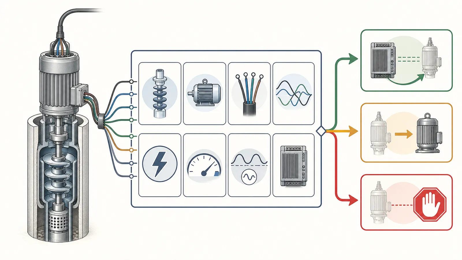
Photograph only what you can safely see
From outside the control enclosure and without removing covers, photograph:
- Pump brand, model, serial number, and any model suffix.
- Motor brand, model, horsepower, voltage, phase, frequency, full-load or service-factor amps, and wire configuration if printed.
- Control-box brand and model, if one is present.
- Existing pressure switch, pressure sensor, pressure transducer, or drive label.
- Pressure-tank brand, model, working-pressure rating, and visible size marking.
- Pressure gauge reading with no fixture open, if the gauge is readable.
- The well record, pump invoice, installation record, or prior service label.
Do not infer the wire count from the number of visible conductors at a wall box. Do not infer the pump model from a controller model. Do not assume a missing label means “standard.” Mark each field as measured, photographed, documented, or unknown.
The minimum identity worksheet
| Field | Your record | Why the professional needs it |
|---|---|---|
| Pump type | submersible / jet / other / unknown | A surface or jet pump can have different starting, priming, and controller limits. |
| Motor type | 1-phase 2-wire / 1-phase 3-wire / 3-phase / unknown | Controller output and programming depend on this classification. |
| Supply voltage | ___ V | A voltage label alone does not prove that the installed circuit delivers the required voltage under load. |
| Phase and frequency | ___ phase / ___ Hz | Phase and frequency affect drive, motor, and curve compatibility. |
| Horsepower | ___ hp | A screening field, not a complete selection rule. |
| Service-factor amps | ___ A | Some controllers are selected by the motor’s maximum service-factor amps. |
| Existing control | pressure switch / control box / drive / unknown | The retrofit may replace or retain different parts depending on the exact system. |
| Motor cable length | ___ ft or unknown | Cable length and wire size can be part of the controller and motor limits. |
| Pump curve | model-specific curve / missing | Hydraulic performance must be checked at a stated flow and head. |
| Priming requirement | no / yes / unknown | An application that needs reliable priming may be excluded by a product manual. |
Pentair’s Pentek Intellidrive manual shows why these fields matter. Its tables distinguish 2-wire, 3-wire, and 3-phase motors, give different horsepower ranges by controller model and motor type, and say the drive should be selected by the motor’s service-factor amps. It also records pump, motor, tank, supply-voltage, and wire-length information for the installer and end user. See the Pentair PN957 manual’s owner-information and electrical-specification tables.
The safe interpretation is simple: a complete label set can support a compatibility review; a horsepower-only label cannot.
2. Screen the controller claim against the exact motor
When a contractor or product page says “works with existing pumps,” translate the statement into checkable fields. A controller must be approved or documented for the motor type, voltage, phase, frequency, service-factor amps, wire configuration, cable length, pump type, pressure sensor, and operating range in your installation.
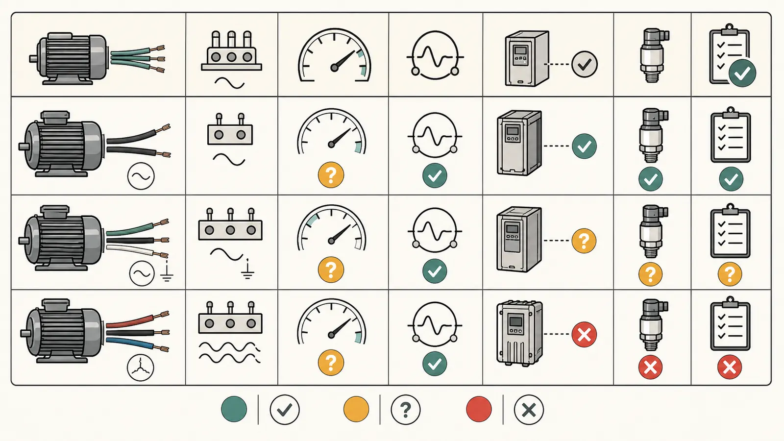
Use a compatibility matrix, not a marketing sentence
| Compatibility gate | Pass evidence | Amber evidence | Stop condition |
|---|---|---|---|
| Pump type | Exact manual names your submersible or approved surface-pump arrangement | Pump type is inferred or a package is being adapted | Manual excludes your pump type or the pump needs unsupported priming |
| Motor wiring | Nameplate and manual agree on 2-wire, 3-wire, or 3-phase | Wire count is unknown or only guessed from the old box | Controller output does not support the exact motor arrangement |
| Phase | Nameplate and controller setup agree | Phase is missing from the label | Proposed controller is for a different phase or motor class |
| Voltage | System voltage and manual range match | Voltage is known nominally but not verified under load | Voltage falls outside the product’s permitted range or circuit scope |
| Horsepower and amps | Both horsepower and service-factor amps fit the controller table | Horsepower fits but amps are missing | Service-factor amps exceed controller rating or are unknown for a critical match |
| Frequency | Pump, motor, and controller are specified for the same frequency | Frequency is absent | Quote mixes incompatible frequency assumptions |
| Sensor and setpoint | Pressure sensor range and setpoint are documented | Existing gauge is mistaken for a control sensor | Sensor is missing, mismatched, or the target pressure exceeds a component limit |
| Cable and wiring | Length, conductor size, grounding, breaker, and local requirements are scoped | Existing wiring is simply called “reusable” | Electrical scope cannot be verified by the qualified installer |
Pentair lists nominal 230 VAC single-phase input, a 190–265 VAC input range, maximum motor-cable length, and model-specific wire and breaker tables for the PN957 controllers. The manual also directs the installer to the pump manual, the National Electrical Code, and local codes for proper wire size. Those details are why “it is already 230 volts” is not a complete electrical answer. Pentair’s installation and wire guidance is specific to that product family; it does not size your circuit.
A “yes” needs a written match
Ask for a line-by-line written match that names the actual existing motor brand and model, states its 2-wire, 3-wire, or three-phase arrangement, voltage, horsepower, and service-factor amps, and names the proposed controller model. The installer should then point to the manufacturer documentation that supports that exact motor type and electrical range. The same scope should say whether the cable, circuit protection, sensor, tank, and pressure components are retained or replaced, and how each is checked for the target setpoint.
That statement is useful because it exposes missing assumptions. It is not a substitute for a licensed electrician or qualified well professional. The installer still needs to verify the equipment and local requirements.
Do not treat built-in protection as a complete system design
Franklin lists dry-run, overload, locked-pump, short-circuit, and undervoltage protections for SubDrive Utility. Pentair also documents dry-run detection and a pipe-fill or prime-time setting in its Intellidrive programming. Those features can be important, but they do not prove that the well yield, sensor location, pressure tank, cable, relief protection, or pump curve is correct. A protection feature can respond to a fault; it cannot make an incompatible motor compatible or create water that the well does not supply.
3. Separate hydraulic fit from electrical fit
A controller can be electrically compatible and still be a poor hydraulic match. Constant pressure means the system changes pump speed or operation to maintain a pressure target as demand changes. The pump still has to move the required water through the well, drop pipe, fittings, filters, valves, and house piping.
Goulds describes a variable-frequency constant-pressure system as monitoring household demand and changing pump speed. Its ResiBoost material also describes a packaged system that includes a pump, controller, and a small tank. That is evidence that constant pressure is a coordinated system function, not proof that a controller can be added to any existing pump without checking the pump’s hydraulic and electrical limits. Goulds’ constant-pressure overview and package description should be read as product-specific documentation.
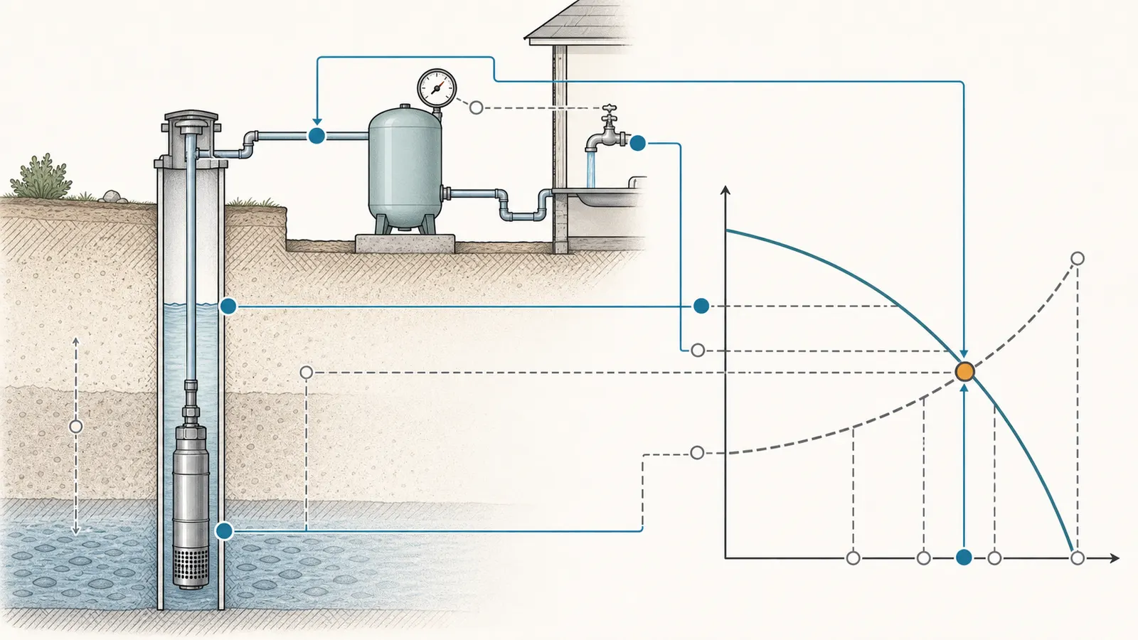
Build a duty point
For comparison purposes, record the flow and total dynamic head the system must deliver. A simple homeowner worksheet is:
total dynamic head = pumping water level + signed elevation term + pressure head + bidder-calculated friction
For ordinary household water, pressure head can be screened as:
pressure head in feet ≈ desired PSI × 2.31
The U.S. Geological Survey’s water-head conversion reference supports the approximate relationship of 0.433 psi per foot of water, or about 2.31 feet per psi. Use it as a conversion, not as a pump-performance claim.
| Hydraulic input | Record | What not to infer |
|---|---|---|
| Required flow | ___ GPM | Do not substitute a pump’s advertised maximum or a nominal series name. |
| Pumping water level | ___ ft below the agreed datum | Do not substitute drilled depth or static level without saying so. |
| Desired pressure | ___ PSI at ___ point | Do not combine a tank-gauge pressure with a second-floor requirement without an elevation translation. |
| Signed elevation | ___ ft | Do not hide the difference between the gauge and the pressure point. |
| Friction loss | ___ ft, with calculation by bidder | Do not invent a residential loss allowance and call the quote proven. |
| Total dynamic head | ___ ft | Do not plot a point until the assumptions and units are visible. |
Example calculation
Suppose a quote says the home needs 10 GPM, a professional record gives a pumping water level 180 feet below the common discharge datum, and the desired pressure at that same datum is 50 PSI. Pressure head is approximately:
50 PSI × 2.31 = 115.5 feet of head
If the bidder calculates 25 feet of friction for the actual pipe, fittings, valves, filters, and distribution segment, the provisional total is:
180 + 0 + 115.5 + 25 = 320.5 feet of head at 10 GPM
The 25-foot term must come from the bidder’s residential calculation. If the bidder has not calculated it, label the result amber. The example demonstrates the method; it does not provide a friction allowance or recommend a pump.
Use pumping level, not drilled depth
Static water level is the water level when the pump is not operating. Pumping water level is the level while water is being drawn. The EPA maintenance guide distinguishes those two observations, which is why a quote should identify which one it uses.
Drilled depth is useful background but is not the same as the lift the pump sees during demand. A pump may be installed at a particular depth while the water level moves above it or below a stable operating level. A quote that uses only “the well is 400 feet deep” has not shown the pumping head. A quote that uses only a shallow static reading may understate the head during a shower, irrigation event, or other peak demand.
Ask the professional to record:
- The common discharge datum, such as the pressure-gauge or tank connection.
- The pressure point the homeowner actually cares about.
- Whether the water-level reading is static or pumping.
- The flow and duration associated with a pumping reading.
- The date, season, and other demand operating during the reading.
- Whether the number came from a well record, prior test, or new measurement.
If the pumping level is unknown, leave it unknown. A transparent unknown is safer than a precise-looking guess.
4. Check well yield, storage, tank, and priming
Constant pressure can make a home feel better while leaving the source problem untouched. A well with limited yield may not supply the flow required by the controller at the time the household needs it. A larger pressure tank may add some stored water, but it is not a substitute for a source-and-demand review.
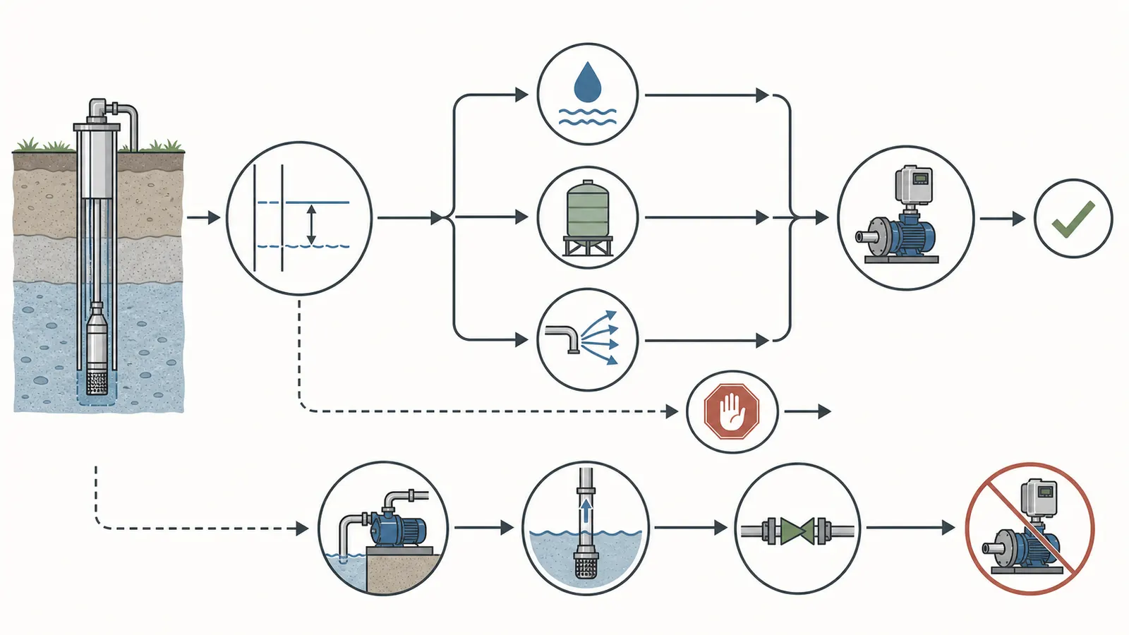
Well yield is a separate gate
Penn State Extension explains that a normal pump can draw a low-yielding well down to a critical point during high use, preventing it from replenishing the pressure tank at the rate water is withdrawn. The same guidance says a larger pressure tank alone provides only a limited increase in stored water and does not solve the underlying low-yield problem. Penn State’s low-yield well guidance is directly relevant to the retrofit question because it keeps the pressure upgrade from being treated as a water-supply upgrade.
Ask for one of these documented bases for the proposed flow:
- A well-yield or pump-test result with drawdown and recovery.
- A current well record with pumping rate and water-level information.
- A professional evaluation that clearly states the flow is a household-demand assumption rather than a measured sustainable yield.
Ontario’s Water Supply Wells manual is a useful government example of the information a pump review can contain: recommended pumping rate, drawdown and recovery, final water level, pump intake setting, and recommended pump depth. It says the installer should consider the yield-test information when determining pump size, pump rate, and intake location. Ontario’s equipment-installation guidance is provincial guidance, not a US national rule; the transferable lesson is to bring the well record and yield evidence into the equipment decision.
Storage may change the outcome
If the well supplies a limited but dependable rate, the right design may involve demand management or intermediate storage rather than simply raising pump speed. Penn State describes intermediate storage as a reservoir supplied by the well and a separate pressure pump that serves the home. It also says the well pump in that arrangement should have a rated capacity slightly less than the well yield. This is a multi-component design with controls, water-quality, freeze, cleaning, and maintenance consequences—not a homeowner add-on to try from a product listing.
Route to a professional design review when the well yield is below the proposed peak flow, the water level approaches the pump intake, the pump runs continuously without recovering pressure, or the existing record is too old to represent current conditions. Do not authorize a higher-pressure setting as a way to make a low-yield well behave like a higher-yield well.
Tank and pressure limits must be visible
Record the pressure tank model, size, rating, and present condition. Ask the bidder to state:
- The proposed constant-pressure setpoint and any minimum or maximum setting.
- Whether the tank is retained, resized, or replaced.
- How the pressure sensor is located, isolated, and protected.
- What limits protect the tank, pipe, fixtures, pump, and other components.
- What happens if a valve is closed, a sensor fails, the well runs dry, or the pump cannot build pressure.
Do not copy a relief-valve value from one manufacturer’s manual into another installation. The component rating, tank arrangement, pump curve, local requirements, and the applicable instructions govern.
Priming is a hard compatibility question for surface pumps
Goulds’ ResiBoost FAQ says some single-phase jet pumps with a start switch are not recommended, says a three-phase model may be used with a three-phase surface motor on incoming single-phase power, and says applications where priming is needed are not recommended. The Goulds FAQ language is a product-specific exception screen.
Therefore:
- A submersible pump is not automatically compatible; its exact motor and controller still need to match.
- A jet pump or other surface pump is not automatically excluded; the specific controller documentation may allow some arrangements.
- A pump that depends on manual or automatic priming needs a written compatibility answer.
- “It runs on the same voltage” does not answer the priming or starting-method question.
If the proposed system needs priming and the selected product documentation says priming applications are not recommended, stop. Request a different design or a professional explanation tied to an explicitly supported product.
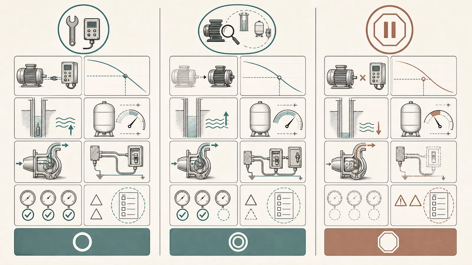
5. Choose the outcome: retrofit, replacement, or stop
Use the strongest evidence available, not the most optimistic label.
| Outcome | Minimum evidence | What the scope should say |
|---|---|---|
| Retrofit screen passes | Exact existing motor and pump identified; controller manual supports type, phase, voltage, amps, and wire arrangement; hydraulic duty point is documented; well yield, tank, sensor, pressure limits, and priming are addressed | Which parts are retained, which are replaced, how the system is protected, and what commissioning readings will be recorded |
| Pump replacement or full-system review | Existing motor cannot be matched, curve is missing, pump is worn, control box is obsolete, hydraulics are inadequate, or electrical work is broader than a controller swap | Exact replacement pump and motor, curve at the stated flow and head, new controls, cable, tank, sensor, pressure limits, and well-yield assumptions |
| Do not proceed yet | Unknown wire or phase, missing service-factor amps, unsupported priming, unresolved low yield, no model-specific curve, unverified tank pressure rating, or electrical scope based on guesswork | The missing fact, who will verify it, and what decision will be revisited after verification |
Retrofit is not the same as “keep everything”
Even a compatible controller may require a new sensor, small tank, protection device, control box change, wiring work, programming, or commissioning. Franklin describes SubDrive Utility as able to work with small pressure tanks or existing units in many applications; that does not establish that the tank in your home is suitable or that all existing controls stay in service. Franklin’s product page supports a retrofit possibility, not a no-change promise.
Goulds’ package description similarly includes a pump, controller, and small tank. That matters when a quote presents “controller only” as though the rest of the system were irrelevant. Ask whether the proposal is a controller retrofit, a controller-plus-sensor-and-tank conversion, or a package that replaces the pump and controls together.
Pump replacement can be the more honest answer
Choose pump replacement or a full-system review when:
- The existing motor is outside the controller’s documented range.
- The existing pump curve is unavailable and the pump model cannot be identified.
- The current pump cannot deliver the desired flow at the documented head.
- The pump is repeatedly tripping, running dry, losing prime, or failing to recover pressure.
- The well yield or drawdown does not support the desired duty point.
- The existing tank, pipe, sensor, or control components are not rated for the proposed pressure.
- The electrician cannot verify the circuit, grounding, cable, disconnect, and protection.
The replacement route is not a failure of the retrofit idea. It is the correct scope when the existing system cannot provide the evidence required for a safe, supportable match.
6. Make safe observations before the appointment
Homeowners can assemble useful evidence without opening a control box or touching the well equipment. The goal is to improve the professional’s starting information.
Safe to observe or record
- Photograph labels from the outside of an enclosure, pump house, or tank.
- Record the pressure gauge with no fixture open, then during a normal shower or other ordinary demand if the gauge can be read from a safe location.
- Note whether pressure is steady, slowly fades, pulses, or drops suddenly.
- Note whether the pump appears to run continuously, cycles rapidly, or stops and restarts.
- Time the flow from an accessible faucet into a known container only if the faucet and water are safe to handle, with no pipe disassembly and no access to the well equipment.
- Record which fixtures are operating when pressure changes.
- Find the well record, prior pump invoice, service report, and controller manual.
- Write down the date, weather or seasonal context, and whether irrigation or other large demand was running.
Stop and assign the work
Do not open an energized control box, variable-frequency drive, pump control, pressure switch, or disconnect enclosure. Do not test live wiring. Do not pull the pump, open the well, remove a pitless adapter, enter a well pit or confined space, change wiring, adjust a pressure switch, defeat a fault, change a drive parameter, or manipulate pressurized fittings just to complete this worksheet.
Pentair warns that the Intellidrive can retain high voltage after power is disconnected, says never to open the box while connected to power, and states that installation, service work, and inspections must be done by a qualified electrician. Read the manual’s electrical-safety instructions. A homeowner-facing compatibility screen should therefore stop at observation and documentation.
The same boundary applies to well work. Ontario’s guidance says equipment installed in a well must be clean, connections must be watertight, and installed equipment must not impair water quality or groundwater. It also recommends that well records be available and equipment be installed to manufacturer specifications. Those are Ontario requirements and best practices, not a US code summary, but they show why opening a well is not a casual diagnostic step. Ontario’s equipment-installation chapter supports assigning downhole and sanitary work to qualified professionals.
7. Ask for a like-for-like written scope
Bring the worksheet and photographs to at least one qualified well professional and, where the electrical work is in scope, a qualified electrician. Ask for a proposal that lets you compare the existing arrangement with the proposed one line by line.
The scope request
Ask the bidder to include:
- Existing equipment identity. Pump, motor, control box or drive, pressure tank, sensor, pressure switch, cable length, voltage, phase, wire configuration, horsepower, service-factor amps, and model numbers.
- Hydraulic design basis. Required flow, pumping water level, common datum, pressure point, desired pressure, signed elevation, pipe and fitting assumptions, friction calculation, and total dynamic head.
- Exact curve. The manufacturer, model, curve document, frequency, and the operating point at the stated flow and head. A horsepower label is not a curve.
- Well basis. Well record, yield or pump-test data, drawdown, recovery, final water level, pump intake setting, and the assumption used if any item is missing.
- Controller match. Controller model, supported motor type, phase, voltage, frequency, service-factor-amp range, sensor range, cable limit, minimum flow or speed behavior, and fault response.
- Tank and pressure scope. Tank model and rating, retained or replaced status, setpoint, pressure relief, check valves, sensor location, and pressure limits for the connected system.
- Priming and surface-pump answer. Whether the pump is submersible, jet, or another surface type; whether priming is required; and the exact manual language or engineering basis for compatibility.
- Electrical scope. Circuit, disconnect, grounding or bonding, cable and conduit, breaker, generator considerations if relevant, and who performs the work under applicable requirements.
- Commissioning record. Startup pressure, flow, voltage, current or service-factor-amp check by the qualified installer, fault history, sensor verification, and any final setpoints. Do not demand that a homeowner take live measurements.
- Exclusions and contingencies. Well rehabilitation, pump pulling, pipe replacement, tank replacement, water treatment, storage, permit or inspection requirements, and what happens if the field findings differ from the quote.
What a complete comparison looks like
| Question | Existing system | Proposed system | Decision impact |
|---|---|---|---|
| Exact pump and motor | Model and label evidence | Model and model-specific documentation | Determines whether this is really a retrofit or a pump replacement. |
| Electrical identity | Voltage, phase, wire, amps, cable | Controller input/output and protection | Rejects horsepower-only compatibility claims. |
| Hydraulic point | Flow, pumping level, pressure, friction | Curve at the same flow and head | Shows whether pressure can be maintained without overstating performance. |
| Well supply | Yield, drawdown, recovery | Proposed rate and dry-run protection | Separates source limitations from equipment limitations. |
| Tank and sensor | Model, rating, condition, location | Retain, resize, replace, and setpoint | Avoids a pressure upgrade that exceeds a component’s scope. |
| Priming | Submersible or surface; priming behavior | Manual-supported application | Captures Goulds-style surface-pump exceptions. |
| Safe work boundary | Accessible labels and readings only | Qualified electrical and well work | Keeps the homeowner out of energized, pressurized, downhole, and confined-space work. |
If a proposal cannot fill a row, the outcome is amber or red depending on the risk. A clean-looking product name is not a substitute for the missing evidence.
8. Use this final decision rule
Before authorizing a constant-pressure retrofit, mark every item below as documented, professionally verified, or not applicable:
- Pump type is known: submersible, jet, or other.
- Motor model, horsepower, voltage, phase, frequency, wire count, and service-factor amps are known.
- Proposed controller model is identified and its manual supports the exact motor arrangement.
- Existing cable, circuit, breaker, grounding, disconnect, and local electrical requirements are included in the scope.
- Pressure sensor or transducer model, range, location, and setpoint are documented.
- Tank model, rating, condition, and retain-or-replace decision are documented.
- Required flow is stated and not confused with a marketing maximum.
- Pumping water level and common hydraulic datum are documented.
- Desired pressure point and signed elevation are explicit.
- Friction is calculated for the actual residential system or clearly marked as unresolved.
- Exact pump curve is plotted at the stated flow and total dynamic head.
- Well yield, drawdown, recovery, and pump intake setting are addressed.
- Priming behavior is compatible with the selected product documentation.
- Pressure limits, relief protection, closed-discharge behavior, and fault response are addressed.
- Commissioning readings will be taken by the qualified installer and recorded.
Use the result this way:
Retrofit candidate: all critical identity, controller, hydraulic, well, tank, priming, and electrical fields are documented or verified, and the exact controller and pump documentation support the proposed arrangement.
Pump replacement or full-system review: the existing motor cannot be matched, the hydraulic curve is inadequate or missing, the source yield is limiting, or the current controls and tank cannot support the proposed setpoint.
Do not proceed yet: any critical field is unknown, the proposal relies on horsepower alone, the product documentation excludes the pump or priming arrangement, or electrical and downhole work has been treated as homeowner troubleshooting.
The purchase-ready next step is a like-for-like written scope with the label photographs, well record, pressure observations, hydraulic calculation, exact curve, controller match, tank decision, and commissioning plan attached. That package lets a homeowner compare proposals on evidence and gives the professional a clear list of facts to verify before the system is opened, rewired, pulled, or pressurized.
Sources and scope
Evidence behind this page
- Franklin Water — SubDrive Utility Variable Frequency Drive
Franklin product-page description for SubDrive Utility. It is a product-specific compatibility statement, not evidence that every motor with the same label will work with every VFD. The page's listed voltage, wire, phase, and horsepower limits must be checked against the exact product documentation.
- Franklin Water — SubDrive Utility Variable Frequency Drive
Franklin's product description. It does not establish that an existing tank is correctly sized, rated, or reusable in a particular home, and it does not replace a tank, pressure, sensor, or installation review.
- Pentair — Pentek Intellidrive Installation and Operation Manual PN957
Pentair PN957 manual for PID10, PID20, PID30, and PID50 Intellidrive models. The table applies to the covered products and does not establish compatibility with another manufacturer or an unlisted motor.
- Pentair — Pentek Intellidrive Installation and Operation Manual PN957
Pentair PN957 specifications and installation instructions. The listed values are product-specific; local electrical requirements and the installed motor and cable govern the actual design.
- Pentair — Pentek Intellidrive Installation and Operation Manual PN957
Pentair product safety instructions. This supports a no-DIY electrical boundary; it is not a substitute for the requirements of the authority having jurisdiction.
- Pentair — Pentek Intellidrive Installation and Operation Manual PN957
Pentair programming parameters for the covered Intellidrive models. It does not establish that another drive or a surface pump can be safely primed by the same settings.
- Xylem / Goulds Water Technology — ResiBoost Brochure
Goulds ResiBoost product FAQ, dated March 2021. These are product-specific recommendations and exceptions, not a universal rule for every surface pump or VFD.
- Xylem / Goulds Water Technology — ResiBoost Brochure
Goulds ResiBoost marketing and FAQ material. It describes that package, not the performance or suitability of an unspecified existing well pump.
- Penn State Extension — Using Low-Yielding Wells
University Extension guidance for low-yielding wells. The article uses this as a system-design warning, not as a tank-sizing recommendation for a particular property.
- Penn State Extension — Using Low-Yielding Wells
University Extension design discussion. It is an option for qualified design review, not a universal retrofit recommendation or an instruction to install a storage tank without water-quality, freeze, controls, and maintenance planning.
- Ontario — Water Supply Wells: Requirements and Best Practices, Equipment Installation
Ontario provincial guidance and regulatory best-practice manual. It is not a national US rule; this article uses it as a documented example of why a well record, yield, drawdown, recovery, and intake location belong in a pump-equipment review.
- Ontario — Water Supply Wells: Requirements and Best Practices, Equipment Installation
Ontario provincial guidance. It does not establish US code requirements or authorize homeowner well work; it supports the documentation and manufacturer-instruction boundary used in this worksheet.
- Ontario — Water Supply Wells: Requirements and Best Practices, Equipment Installation
Ontario provincial requirements and best practices. The article uses these as a regional example of sanitary and watertight installation concerns, not as a nationwide code statement.
- Xylem / Goulds Water Technology — ResiBoost Brochure
Goulds ResiBoost FAQ. The statement is limited to that product package and does not prove compatibility of an existing pump, motor, or well system.
- U.S. Geological Survey — Use of Submersible Pressure Transducers in Water-Resources Investigations
USGS hydrologic conversion reference. The article uses this as an approximate conversion for ordinary household water, not as a pump-performance or residential-friction claim.
- U.S. EPA — Preventive Maintenance Tasks for Tribal Drinking Water Systems Guide Booklet
EPA guide for tribal drinking-water systems. The article uses the definitions and recordkeeping concept as a reference, not as a private-well regulatory requirement.