Why Does My Well Pressure Tank Keep Losing Air?
A sourced homeowner decision flow to separate a leaking valve, failed bladder, corroded tank, legacy air-over-water tank, or pressure fault elsewhere.
The short answer
Repeated air loss is not automatically a bad tank. First identify whether the vessel is a bladder/diaphragm or legacy air-over-water design, then document cut-in, cut-out, visible leaks, pump cycling, and the time-to-loss. An empty-tank precharge reading is a service measurement: it must follow the exact manual and stop if the tank is corroded, damaged, or losing air. A leaking valve may be repairable; a failed bladder, corroded shell, or unexplained pressure fault needs professional diagnosis.Observation flow
What is the system doing?
Choose the closest visible pattern. Stop immediately for sparking, hot wiring, uncontrolled pressure, or a damaged tank.
Why Does My Well Pressure Tank Keep Losing Air?
Repeated air loss is not automatically a failed tank. The right first question is whether the vessel is a bladder/diaphragm tank, an older air-over-water tank, or a different pressure vessel entirely. Then separate four observations: where air may be escaping, what the tank does to pump cycling, what an empty-tank precharge measurement shows, and how quickly the symptom returns.
The safest homeowner outcome is an evidence packet, not another blind air top-up. Record the tank label, tank type clues, pressure-gauge behavior, cut-in and cut-out if they can be observed without opening equipment, visible wetness or corrosion, and the date of each recurrence. Have a qualified well or plumbing professional perform the empty-tank precharge measurement and any air-valve work. Amtrol warns that adding pressure to a tank with corrosion, damage, diminished integrity, a history of air loss, or reduced pump cycle time can create a rupture or explosion hazard. (Amtrol Well-X-Trol installation instructions)
1. First decide what “losing air” means
Homeowners use “losing air” for several different events. They may mean the pressure at the tank air valve is lower than the last time someone checked it. They may mean the pump runs every few seconds after air was added. They may mean the house pressure falls overnight. They may mean water came out of the air valve. These are not interchangeable findings.
Use this distinction before you decide “replace the tank.”
| What you observed | What it establishes | What it does not establish | Safest next step |
|---|---|---|---|
| Air reading is lower on a repeat check | The reading changed under the two test conditions | It does not identify a valve leak, bladder failure, shell leak, or pressure fault | Repeat the log with the same method and have the exact manual followed |
| Pump starts and stops rapidly | The system may have insufficient effective drawdown or a control/system problem | It does not prove the bladder has ruptured | Stop repeated cycling and request professional diagnosis |
| Bubbles appear at the air valve, cap, or accessible fitting during an authorized leak check | A service point may be leaking externally | It does not prove the tank shell or bladder is sound | Have the valve, core, cap, or fitting evaluated; do not keep inflating a compromised tank |
| Water comes from the air valve | On a bladder tank, the air-water separation may have failed | It does not identify whether the entire vessel can be safely serviced | Stop the air top-up plan and request tank/bladder service |
| Exterior rust, bulging, weeping, or a wet floor is present | The vessel or connection may have lost integrity | It does not tell you how much metal strength remains | Keep clear, protect the area from water damage, and call a qualified professional |
| Precharge is low after the tank was safely emptied and tested | The tank is not holding the documented charge under that service test | It does not alone distinguish a valve, bladder, shell, or connection fault | Give the result and the exact model manual to the professional |
| Precharge holds but the house loses pressure | The tank is not proven to be the source of the reported pressure loss | It does not prove the pump, check valve, well, or plumbing is healthy | Move the investigation to the rest of the system |
The table is deliberately cautious. A symptom narrows the next question; it does not authorize a pressurized repair. Washington State Department of Health lists rapid cycling, changed tank sound, water at the air-charging valve, and rusty or stale water as clues associated with a waterlogged bladder tank, but its technical tip is a troubleshooting aid, not a license to open or repressurize a tank. (Washington State Department of Health DOH 331-342)
2. Identify the tank type before using any air advice
The phrase “pressure tank” covers designs with different normal behavior. Connecticut Department of Public Health describes modern bladder tanks and older non-bladder galvanized tanks as separate types. In a non-bladder tank, air is in contact with water and is gradually absorbed, so periodic air management is part of the design. In a bladder tank, a membrane separates the air and water; the agency says waterlogging occurs when the bladder or diaphragm fails. (Connecticut Department of Public Health’s private-well guidance)

Modern bladder or diaphragm tank
Look for a factory label, a model number, and an air valve near the top. A steel Well-X-Trol-style tank may be painted or coated; a WellMate-style tank may use a nonmetallic vessel. Those appearances are clues only. The label and installed manual control the diagnosis, pressure rating, connection details, and service instructions.
On this design, repeated loss of precharge can come from an external air-valve or fitting leak, a damaged cap or core, a bladder/diaphragm problem, a shell or connection leak, or a measurement made while the tank still contains water. Water at the air valve is a particularly important finding: it is not a reason to add more air and continue operating as though the tank were healthy.
Older galvanized air-over-water tank
An older galvanized tank may be large, horizontal or vertical, and lack the internal membrane found in a bladder tank. Its air charge naturally migrates into the water, so “it needs air again” can be normal for the design rather than proof of a ruptured bladder. The same Connecticut guidance warns that the wet-dry cycling inside these tanks accelerates corrosion and can lead to pinhole leaks. (Connecticut Department of Public Health’s private-well guidance)
Do not use a bladder-tank replacement rule for a legacy air-over-water tank. The decision may involve an air-volume control, snifter valve, air injector, tank tee, corrosion condition, or conversion to a different system design. Those are component and installation questions for a professional who can identify the actual arrangement.
A controller or tank that is not a conventional pressure-switch system
If the pump system uses a variable-frequency drive, electronic controller, pressure transducer, or constant-pressure package, do not assume that the visible tank should be analyzed as a 30/50 or 40/60 system. Pentair describes a constant-pressure system that changes pump motor speed using pressure-transducer feedback. That is a different control loop from a fixed-speed pump that starts and stops at two pressure-switch settings. (Pentair constant-pressure system description)
Record the controller model and ask for the current controller and tank instructions. Xylem’s Aquavar manual, for example, has a separate constant-pressure layout with a pressure transducer and diaphragm tank and calls for controller-specific compatibility and programming. (Xylem/Goulds Aquavar manual) A familiar pressure band is not a substitute for that system’s documentation.
3. Apply the stop-work boundary before measuring anything
This is a high-safety diagnostic. A pressure tank stores energy in compressed air and pressurized water, and it is connected to electrical pump controls. The homeowner-safe portion is observation and documentation from a safe position. Service work belongs to a qualified professional following the installed tank, pump, and control manuals.
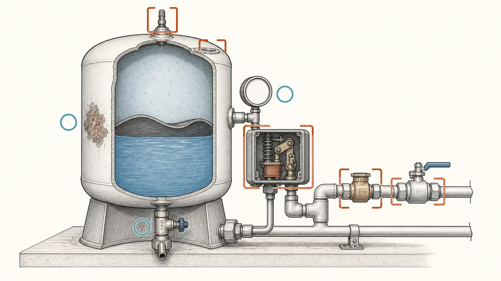
Do not:
- open an energized pressure-switch or pump-control enclosure;
- test live wiring or bypass a pressure switch;
- open the well, pull the pump, enter a well pit, or enter another confined space;
- loosen a tank tee, flange, drain, relief valve, gauge, or other pressurized fitting;
- remove the air-valve core or deliberately bleed a tank that may be compromised;
- add compressed air or nitrogen because the reading “looks low”;
- adjust cut-in, cut-out, relief-valve settings, or controller parameters;
- rely on tapping, tipping, or shaking a tank as proof that it is safe to pressurize;
- keep operating a tank that is bulging, badly corroded, leaking, or wetting the floor.
Amtrol’s manual says the tank should not be adjusted or re-pressurized when there has been a loss of air, visible exterior corrosion, or a reduction in pump cycle time compared with the initial setting. It also says only licensed professionals should check, adjust, or recharge precharge. (Amtrol Well-X-Trol installation instructions) Pentair likewise says the tank, fittings, and connected system must not be disassembled until air and fluid pressures are completely discharged. (Pentair WellMate installation instructions)
Jurisdiction and installation matter here. Licensing, relief-device, installation or replacement, and emergency-shutoff requirements can vary with local code and the installed system manual. Amtrol requires licensed-professional installation, directs installers to follow applicable local and state codes, and says relief protection must satisfy the lower of the local-code requirement or the product’s maximum working pressure. If the local authority or the tank and pump manuals differ from this article, follow those requirements and use a qualified professional; do not improvise a relief-device change or emergency shutoff. (Amtrol Well-X-Trol installation instructions)
If water is actively spraying, the tank is moving, the floor is flooding, the pump will not stop, or the pressure gauge is beyond the tank’s labeled operating range, keep people away and use the system’s normal emergency shutoff only if you can do so without opening equipment or approaching a hazardous leak. Otherwise call for urgent professional help. Do not remove or defeat a relief valve. Pentair requires an adequately sized relief device and says it must not be isolated from the tank by a check valve. (Pentair WellMate installation instructions)
4. Build the evidence packet in a low-risk sequence
The goal is to make the recurrence measurable and to keep observation separate from service. A useful packet can be assembled without opening the tank or control box.
Step 1: Photograph or transcribe the labels
Record the tank manufacturer, model, serial number if visible, nominal volume, maximum working pressure, temperature limits, and any warning label. Also record the pump, controller, pressure switch, gauge, and any visible air-volume-control or injector components. Photograph the piping from a safe distance without removing insulation or covers.
Do not infer tank construction from color, size, or the presence of a top cap. A professional needs the exact model to select the correct precharge rule and replacement part.
Step 2: Observe the normal cycle without touching controls
From a safe position, note the pressure gauge when the pump starts and stops, if the gauge is readable and the events are obvious. Write down the apparent cut-in and cut-out, whether the gauge needle is steady or erratic, and whether the pump cycles once during a normal water use or repeatedly in a short interval.
Do not manufacture a precise reading from a dirty gauge. Write “about,” “not readable,” or “not observed” when appropriate. A guessed 40/60 setting can send a service call toward the wrong precharge target.
Step 3: Inspect only external, de-energized-looking clues
Without opening covers or touching the air valve, look for active drips, a wet floor, mineral tracks, rust blisters, paint lifting, bulging, a loose-looking cap, or wetness around accessible joints. Do not wipe away evidence before photographing it. Do not wrap or remove insulation to inspect a tank; legacy-tank guidance warns that insulation can hide small leaks, but disturbing a tank or its fittings is not a homeowner repair step. (Connecticut Department of Public Health’s private-well guidance)
Step 4: Record water symptoms separately
Note low pressure, rusty or stale water, spurting air at faucets, cloudy water, or a change in pump noise. A water-quality or odor change is not proof of a tank failure. If you suspect the well water is contaminated, stop drinking it and contact the local health department or other appropriate authority for testing and treatment guidance. Tank diagnosis does not substitute for private-well water testing.
Step 5: Ask for the empty-tank precharge reading
Write this as a requested service measurement, not a DIY instruction: “Please verify the tank precharge with the pump power off, water pressure released, and tank empty, using the exact tank manual.” Pentair’s WellMate guidance requires the tank to be empty and gives a product-specific 4-psi offset below the low-pressure limit. Amtrol’s Well-X-Trol example uses 2 psi below cut-in. (Pentair WellMate FAQs, Amtrol Well-X-Trol installation instructions)
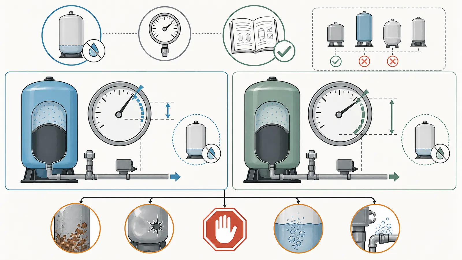
Those numbers conflict because they belong to different product instructions. They are not a universal rule. The professional should record the exact model, the pressure-switch setting used, whether the tank was truly empty, the gauge used, the observed precharge, and whether the reading changed after the valve was isolated or tested.
5. Use the decision tree: valve, bladder, shell, legacy tank, or elsewhere
This is the central decision surface. Move from observable evidence to the next bounded action; do not jump from “low air” to “new tank.”
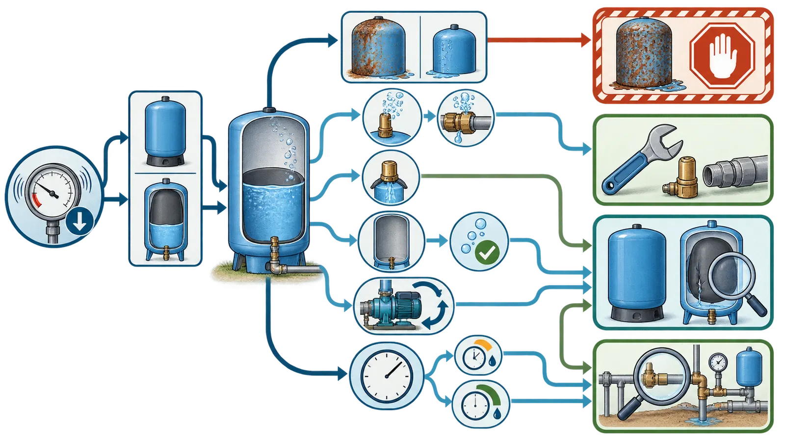
| Evidence branch | Most defensible interpretation | What to ask the professional to verify | Likely action category |
|---|---|---|---|
| Tank is a bladder/diaphragm design; no corrosion; air-valve cap/core or fitting shows an external leak | Air may be leaving through a service point rather than through the tank body | Valve core, cap seal, fitting threads, flange or connection, and whether the tank still passes an integrity check | Repair or replace the leaking external service part if the tank is sound; recheck to the exact manual |
| Water escapes at the air valve on a bladder tank | Air-water separation may have failed and the tank may be waterlogged | Bladder/diaphragm condition, shell condition, model repairability, and safe depressurization | Tank replacement or an approved bladder service by a qualified professional |
| Rapid cycling plus low/no precharge after a proper empty-tank service measurement | The tank is not providing the expected air cushion, but the cause is not yet identified | Valve leakage, bladder failure, shell corrosion, gauge accuracy, pressure-switch settings, and drawdown | Stop repeated top-ups; repair or replace only after the cause and vessel condition are established |
| Exterior corrosion, rust blisters, bulging, weeping, or unexplained recent air loss | The vessel’s integrity is uncertain | Tank age/model, maximum pressure, shell condition, relief protection, and replacement path | Stop repressurization; professional replacement or urgent safety evaluation |
| Older galvanized air-over-water design; charge returns low over time; no bladder | Air absorption may be part of normal design behavior | Air-volume-control arrangement, corrosion, pinholes, and whether modernization is appropriate | Service the air-management system or evaluate replacement/conversion; do not apply bladder logic |
| Precharge is correct and stable under the professional’s test, but house pressure still falls | The tank is less likely to be the source of that pressure loss | Downstream leaks, check-valve behavior, pump delivery, well yield, controls, and gauge accuracy | Professional investigation elsewhere in the well system |
| Pressure changes only when a controller or variable-speed pump changes state | Conventional pressure-switch assumptions may not apply | Controller fault history, transducer, programming, tank compatibility, and current controller manual | Controller-specific diagnosis and settings review |
The first row is the only branch that may lead to a simple valve or fitting repair, and even there the tank’s condition matters. Amtrol’s replacement-bladder instructions use soapy water at the drain fitting threads, air-valve core, and flange joints to locate leaks, but those instructions are for qualified service. They also warn that a poorly sealed valve cap can cause loss of precharge. (Amtrol replacement-bladder instructions)
The “elsewhere” branch is important. If the tank holds the documented precharge when correctly isolated and empty, that result lowers the probability that the tank is the air-loss source. It does not prove the check valve, pump, well, pressure switch, or house piping is healthy. That is an inference from the test boundary, not a manufacturer diagnosis; preserve the evidence and widen the service investigation.
6. Measure time-to-loss without turning it into a false diagnosis
“It loses air quickly” is useful only when “quickly” is recorded. Use the same date format, the same observation conditions, and the same professional measurement method each time. Do not compare a reading from a full, pressurized tank with a reading from an empty tank.
Repeated-air-loss log
| Date/time | Tank or pump event | Gauge/cut-in/cut-out observed | Visible leak or corrosion | Air-valve finding | Empty-tank precharge | Days since prior service | Action taken |
|---|---|---|---|---|---|---|---|
| __________ | __________ | __________ | __________ | __________ | __________ | __________ | __________ |
| __________ | __________ | __________ | __________ | __________ | __________ | __________ | __________ |
| __________ | __________ | __________ | __________ | __________ | __________ | __________ | __________ |
| __________ | __________ | __________ | __________ | __________ | __________ | __________ | __________ |
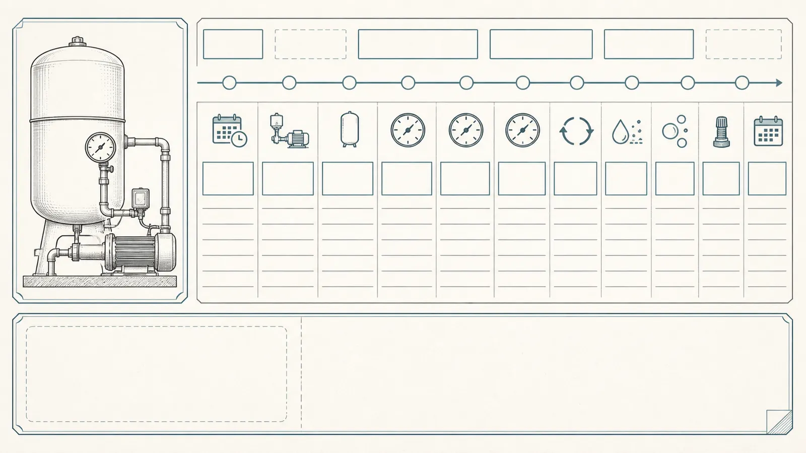
Add these fixed identity fields at the top of the log:
- Tank manufacturer/model: __________________________________
- Tank serial or installation date, if known: __________________
- Tank type: bladder/diaphragm / galvanized air-over-water / unknown
- Pump and controller model: _________________________________
- Pressure-switch or controller setting shown in documentation: __________
- Gauge location and whether it appears readable: ______________
- Professional or company recording the service measurement: __________
Calculate the recurrence interval
Use a simple calendar calculation:
time-to-loss = date of the new low or failed precharge condition − date of the prior documented service condition
If a professional records a precharge value (P_1) at one service visit and (P_2) at the next, you may also record:
observed change = (P_1 - P_2) psi over the logged interval
Do not convert that into a guaranteed leak rate unless the test conditions are equivalent: same tank state, same gauge or a known gauge comparison, same pressure-switch setting, and no intervening service. The number is a comparison aid, not proof of a particular failed component.
Patterns are more useful than a single value:
- A loss immediately after a valve or cap was disturbed points the professional toward the service point, but does not clear the tank.
- A recurring low reading with water at the air valve points toward a bladder/diaphragm issue on a bladder tank.
- A low reading plus corrosion or reduced pump cycle time triggers the no-repressurization warning.
- A legacy tank that gradually becomes waterlogged may be showing normal air absorption combined with a corroded or failing air-management system.
- A stable tank reading with continuing house pressure loss points the investigation beyond the tank.
7. Choose repair, replacement, or a wider system investigation
When a valve or fitting repair is plausible
A valve core, valve cap, or accessible fitting is a plausible repair target when the professional can show that air is escaping at that part, the tank has no concerning corrosion or damage, and the pressure vessel remains within its documented operating limits. A cap or core repair is not the same as adding air indefinitely. The repair should be followed by a documented leak check and a repeat of the exact model’s precharge procedure by the qualified service provider.
Do not remove the core yourself to “see what happens.” A pressurized air valve can release energy, and a valve leak does not rule out a weak shell or failed bladder.
When replacement or bladder service is plausible
Replacement becomes more defensible when a bladder tank shows water at the air valve, persistent rapid cycling with a properly performed low/no-precharge result, visible tank damage, or corrosion that makes the vessel’s integrity uncertain. Washington State Department of Health says waterlogged bladder tanks should be replaced. (Washington State Department of Health DOH 331-342)
Some tank families have replaceable bladders, but “replaceable” does not mean homeowner-safe. Pentair says a WellMate air cell can be replaced only after the tank is removed and disassembled, and Amtrol’s replacement-bladder instructions require isolation, draining, bleeding remaining air, lifting equipment, and professional installation. (Pentair WellMate FAQs, Amtrol replacement-bladder instructions)
The replacement decision should include more than nominal gallons. Ask the professional to match the exact model’s published drawdown at the verified cut-in/cut-out, maximum operating pressure, connection and orientation, temperature range, support, relief protection, and service access. A larger tank is not automatically the correct tank, and a new tank does not cure a bad pressure switch, check valve, pump, or well-side problem.
When the older tank needs a different plan
For an air-over-water tank, repeated air loss may be ordinary absorption, but a charge that disappears unusually fast can signal a failed air-volume-control arrangement, air injector issue, pinhole leak, or advanced corrosion. The Connecticut guidance explains both the normal absorption mechanism and the corrosion risk from repeated wet-dry cycling. (Connecticut Department of Public Health’s private-well guidance)
Ask for a decision that names the existing design, explains whether it can be safely serviced, and compares continued maintenance with a correctly selected replacement. “Add air” is a maintenance action only when the tank and air-management equipment are known to be appropriate and sound.
When the tank is not the likely cause
If the professional documents a stable empty-tank precharge and no external tank leak, ask for the next pressure-loss checks. Depending on the system, that may include an isolated house-side leak check, check-valve behavior, pump delivery at pressure, pressure-switch or controller operation, well yield, gauge accuracy, and any treatment equipment that can restrict or lose pressure. This list is an investigation scope, not a homeowner test sequence.
The key handoff is: “The tank was tested under these conditions and did or did not hold charge; please investigate the remaining pressure path.” That avoids paying for a tank replacement that cannot solve a pump-side, well-side, or plumbing-side fault.
What to hand the service professional
Bring a compact packet rather than a conclusion. Include:
- clear photographs or transcriptions of tank, pump, controller, gauge, and pressure-switch labels;
- tank type classification and the clues used to make it;
- observed cut-in and cut-out, with “not readable” when appropriate;
- dates when air was added or a service visit occurred;
- the time-to-loss log and any pump short-cycling observations;
- photos of corrosion, mineral tracks, wetness, bulging, or floor damage;
- whether water was ever observed at the air valve;
- the exact tank manual or manufacturer link;
- any known water-quality, freezing, treatment, or power events;
- the requested answer: valve/fitting, bladder/diaphragm, shell, legacy air management, or pressure loss elsewhere.
Ask the professional to return five documented findings: tank type and model, actual cut-in/cut-out or controller behavior, empty-tank precharge and test conditions, visible or confirmed leak location, and the recommended action with its safety reason. If replacement is recommended, ask for the published drawdown and pressure-rating match, not only a nominal gallon number.
The decision is complete when the evidence explains both the air loss and the safe next action. Until then, repeated air top-ups are a symptom treatment—not a diagnosis—and a corroded or compromised pressure tank should not be re-pressurized to see whether the problem goes away.
Sources and scope
Evidence behind this page
- Connecticut Department of Public Health — Home Cellar Dwellers
Connecticut private-well homeowner guidance published in 2012; it supports the tank-type distinction and legacy air-management explanation, not a universal service interval or a diagnosis of a particular tank.
- Connecticut Department of Public Health — Home Cellar Dwellers
The document's discussion of older galvanized, non-bladder tanks; it does not establish that every galvanized tank is unsafe or that every leak is visible.
- Washington State Department of Health — DOH 331-342 Troubleshooting Bladder Pressure Tanks
Washington Office of Drinking Water technical tip for bladder pressure tanks; the clues are screening observations, not a substitute for a model-specific inspection or a safe pressure test.
- Washington State Department of Health — DOH 331-342 Troubleshooting Bladder Pressure Tanks
The technical tip's simplified bladder-tank cycle for small drinking-water systems; it is explanatory and does not define the settings of an individual installation.
- Amtrol — Well-X-Trol Residential Pre-Pressurized Well Tanks Installation & Operation Instructions
Amtrol Well-X-Trol WX-101 through WX-350 instructions; the 2-psig example and service boundary are product-specific and must not be generalized to another tank.
- Amtrol — Well-X-Trol Residential Pre-Pressurized Well Tanks Installation & Operation Instructions
Amtrol's installation and safety warnings for the referenced Well-X-Trol product family; they establish a conservative stop-work boundary and show why local code and the installed tank manual control, not a universal homeowner rule.
- Pentair — WellMate UT, HP & SP Series Installation Instructions and WellMate FAQs
Pentair WellMate UT, HP, and SP instructions; the 4-psig example applies to that product family. The FAQ's procedure is a service boundary, not permission to work on a corroded or damaged tank.
- Pentair — WellMate UT, HP & SP Series Installation Instructions
Pentair's WellMate UT, HP, and SP installation instructions; this is manufacturer guidance for the referenced tanks and does not state a national plumbing code.
- Amtrol — Well-X-Trol WX Series Replacement Bladder Instructions
Amtrol's replacement-bladder service instructions; the leak-check method is presented for professional service and does not make a homeowner repair or valve-core replacement safe on a compromised tank.
- Pentair — WellMate UT, HP & SP Series Installation Instructions
The example table and note in Pentair's referenced WellMate manual; values apply only to the stated product and application conditions.
- Pentair — Pentek Intellidrive Constant Pressure Systems
Pentair's product description of its Intellidrive constant-pressure system; it supports the system-type branch and does not prescribe a universal tank size for other variable-speed products.
- Xylem/Goulds Water Technology — Aquavar Controller Programming Manual
The Aquavar manual's constant-pressure application section; its requirements are product- and application-specific and do not replace the current manual for another controller.
- Pentair — WellMate FAQs
Pentair's WellMate FAQ and WellMate tank family only; it supports the service boundary and demonstrates why the exact tank instructions matter.