Why Is My Well Pressure-Tank Relief Valve Leaking?
Identify the wet valve or fitting, record pressure and timing without opening controls, and know when a leaking well-tank relief valve requires a shutdown and qualified help.
The short answer
Identify wet point: cold-water relief valve, Schrader valve, fitting, or water-heater T&P valve. Record pressure, pump cycling, and leak timing from a dry location. Never cap, plug, isolate, or adjust safety devices. For abnormal pump pressure, shut off pump power at a dry, accessible disconnect. Close water only if safely reachable and it will not isolate tank from its relief valve. For hot discharge, follow water-heater shutdown guidance. Call qualified help for hot discharge, uncertainty, corrosion, electrical exposure, or contamination.Observation flow
What is the system doing?
Choose the closest visible pattern. Stop immediately for sparking, hot wiring, uncontrolled pressure, or a damaged tank.
Why Is My Well Pressure-Tank Relief Valve Leaking?
If water is coming from a valve near a private-well pressure tank, first identify the wet component. The cold-water pressure relief valve is not the same part as the small Schrader air valve on top of a tank, a leaking threaded fitting, or the temperature-and-pressure (T&P) valve on a water heater. Dry the outside of the assembly, watch where the first bead appears without touching the valve, and record the pressure gauge and pump timing from a safe distance.
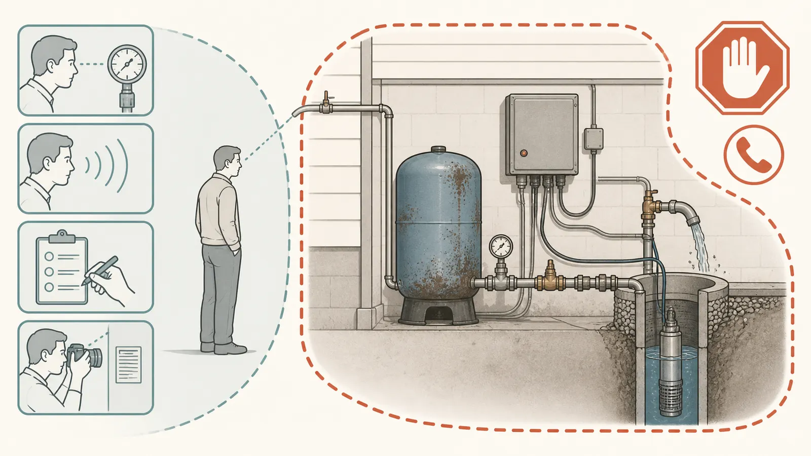
Do not cap, plug, clamp, isolate, remove, or “test” the relief valve. Do not open an energized control box, test live wiring, open the well, pull a pump, enter a well pit or other confined space, loosen pressurized fittings, or add air to a tank that is corroded, damaged, or losing air. If the pump will not stop, pressure is rising beyond the known operating range, the tank or piping is corroded, water is spraying, the leak is continuous, water is near electrical equipment, or you cannot identify the wet point, shut off well-pump power only if you can do so from a dry, accessible location without approaching water or exposed wiring. Close the home water supply only if it is dry and safely reachable and will not isolate the tank from its relief device. For hot discharge from a water heater, keep clear and follow that appliance's shutdown instructions rather than applying the well-pump procedure. Otherwise, leave the system alone and call a qualified well or plumbing professional.
Do not taste, sample, or use uncertain discharge or standing water around the assembly as drinking water. If the well or water may have been affected by flooding, sewage, chemicals, unusual color, taste, or odor, use a safe alternate source and contact your local health or environmental department and a qualified well professional before resuming drinking use. The CDC's private-well guidance says not to drink well water that may be contaminated and directs owners to health-department guidance.
1. Use the stop-and-call boundary first
A leaking relief device can be an ordinary failed valve, but it can also be the only visible evidence that a pump-control or over-pressure problem is developing. The safe homeowner task is observation and documentation. Repair, replacement, precharge adjustment, pressure-switch adjustment, electrical diagnosis, tank removal, and any work that exposes pressurized equipment belong to a qualified professional.
The model-specific reason for caution is clear in AMTROL's precharged well-tank manual: its warning says a pressure tank can corrode, fail, leak, flood, or in rare cases explode, and it assigns installation, inspection, and service to a licensed professional. The same manual warns against adding precharge to a corroded or damaged tank. That is not proof that your tank is unsafe; it is a reason not to create a new pressure event while investigating a wet valve.
Shut down now when any of these is true
- The gauge is above the tank, valve, or system pressure shown on the equipment label, or the reading is still climbing while the pump runs.
- The pump runs continuously, does not reach its usual cut-out, starts and stops rapidly, or the relief valve discharges as the pump runs.
- The discharge is a stream, spray, or repeated flow rather than a single wet bead, or the amount is enough to flood the room.
- The tank, tank tee, relief valve, gauge connection, or nearby pipe shows bulging, deep rust, pitting, cracking, movement, or a damaged discharge outlet.
- Water is reaching a control box, switch, outlet, extension cord, motor, or other electrical equipment.
- The water is hot, the wet point is on a water heater, there is a gas appliance concern, or anyone could be scalded.
- You would need to remove a cover, use a wrench on the tank or valve, press the valve lever, add air, change a pressure-switch setting, or work in a wet or confined space to continue.
If the pump disconnect or breaker is in a dry, accessible place and you can operate it without stepping into water or touching exposed conductors, switch off pump power and label the system “do not restart.” Do not rely on a pressure switch to stop a pump that is already behaving abnormally. If the electrical disconnect is wet, damaged, inside the hazard area, or unfamiliar, leave it alone and call for help. Tell the professional whether the home still has water, whether the pump is running, and whether the gauge is rising.
2. Find the first wet point
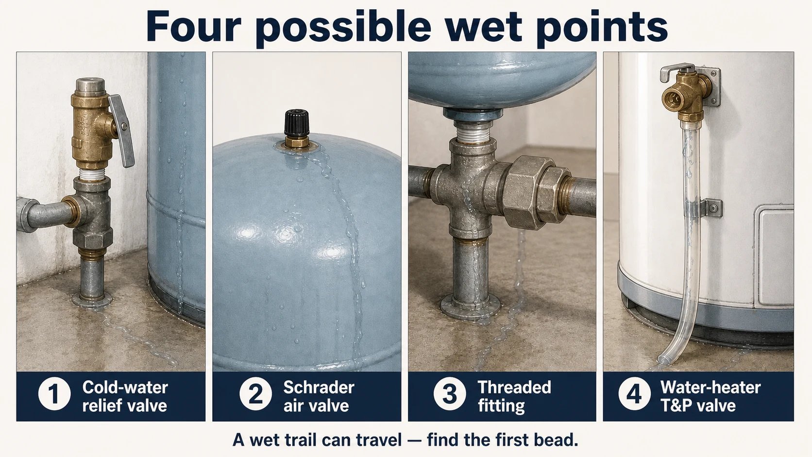
Water can run along a pipe or the outside of a valve, so the lowest drip is not necessarily the leak. If conditions are dry and calm, close nearby fixtures, keep the pump and controls closed, and use a dry paper towel or clean tissue to touch the outside of each accessible connection—not the valve outlet or moving parts. Stop if the paper becomes wet near an electrical component, if the surface is hot, or if the equipment is corroded. Photograph the dry layout and the label before moving anything.
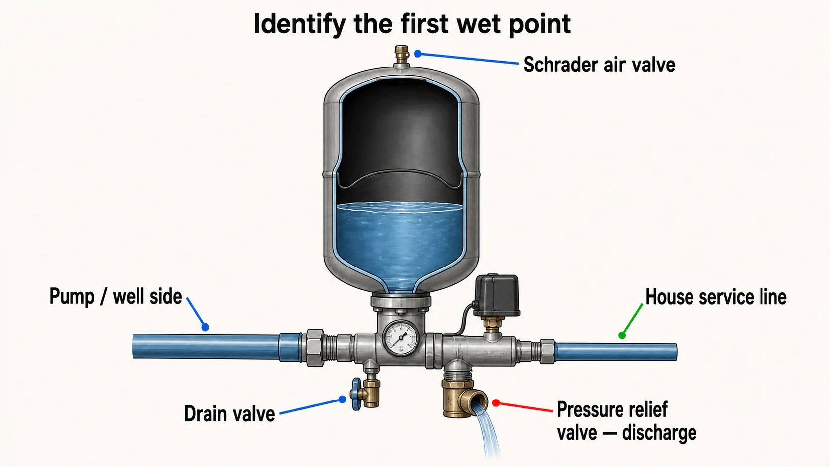
| First wet point you can see | What it usually is | What the observation can tell you | Safe next step |
|---|---|---|---|
| Small outlet or discharge opening on the tank-side piping near the tank tee; water emerges from the valve body or outlet | Cold-water pressure relief valve | The safety device may be lifting from excess pressure, leaking at its seat, or failing at its connection; observation alone cannot separate those causes | Record gauge pressure and timing; do not cap, plug, isolate, or operate the valve; escalate if it continues or pressure is abnormal |
| Small capped stem on the top of the tank, similar to a tire valve | Schrader or air-charging valve | This is associated with the tank air space, not the normal water-discharge path of a relief valve; a wet stem or missing cap may indicate a valve or connection problem | Do not press the stem or attach a compressor during diagnosis; ask a qualified professional to assess the tank and precharge boundary |
| Nut, threaded joint, union, gauge port, drain connection, or tank-tee seam | Fitting or connection leak | The safety valve may only be nearby; a fitting leak does not prove the relief valve opened | Photograph the exact joint and whether the leak changes during pump operation; do not tighten a pressurized or corroded connection |
| Discharge tube from a valve installed in the top or side opening of a water heater; water may be hot | Water-heater T&P valve | This is a different safety device protecting a hot-water appliance from excessive temperature or pressure | Keep clear of the outlet and hot water; shut down according to the water-heater manual only if the controls and shutoffs are safely accessible; call a qualified professional |
| Water begins above the visible valve and tracks down | Upstream fitting, gauge, switch sensing line, or tank connection | The visible valve may be dry and only carrying runoff | Dry and observe from a safe distance; give the professional a photo showing the complete assembly |
Pentair's WellMate FAQ identifies the tank tee, gauge, pressure relief valve, drain valve, pressure switch, union, and service-line isolation valve as separate system components. It also locates the air-cell check at the valve stem on top of the tank, after pump power is off and tank water is drained. That distinction is useful for identification; it is not an invitation to drain or service a pressurized tank as a homeowner.
For the cold-water assembly, AMTROL's manual places the relief valve at the connection of the well tank to system piping. Many installations use a tank tee with a gauge and pressure switch nearby, but your piping may differ. Follow the actual valve outlet and the tank or installation label rather than assuming that a familiar-looking brass part is the relief valve.
3. Record pressure without opening controls
The pressure gauge is the most useful homeowner observation if it is readable, dry, intact, and already installed. Do not remove it, tap it, recalibrate it, or open the pressure switch cover. Do not touch electrical terminals. A gauge reading is a snapshot, not proof that every part of the system sees the same pressure, especially when the gauge, tank, and switch are separated by piping or elevation.
Write down the system's known operating range from a service record, label, or prior professional invoice if you have one. Call the lower number the known cut-in or pump-start pressure and the higher number the known cut-out or pump-stop pressure. Do not substitute a common range from the internet. Penn State Extension gives a 40-psi stop and 20-psi restart as an example of a pressure-tank cycle, but explicitly using it as an example is important: the numbers do not establish your installation's settings.
A safe observation procedure
- Make sure all visible water around the gauge, tank tee, and controls is wiped up only from a dry, accessible surface. If doing so would put your hand near electricity, hot water, spray, or a corroded fitting, skip it.
- With no one using water, photograph the gauge and note the time. Record whether the pump is silent, running, or cycling. Do not touch the pressure switch to find out.
- If the pump is already off and the system is stable, record whether the leak is absent, a single bead, a slow drip, or a continuous flow. Do not lift the relief-valve lever to “see if it resets.”
- If a normal, dry fixture can be opened without entering the hazard area, note whether the gauge falls and whether the pump starts at the previously known cut-in point. Close the fixture and record whether the pump stops at the known cut-out point. Do not run the test if water could reach electrical equipment, the pump is already abnormal, the tank is corroded, or the professional boundary has been reached.
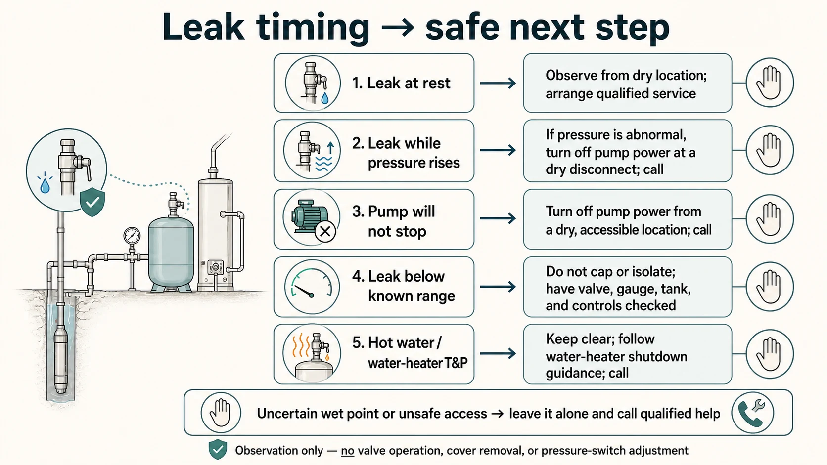
- Note the sequence: did the relief valve leak before the pump started, while pressure rose, as the gauge approached its usual cut-out, after the pump failed to stop, or only after a hot-water event elsewhere?
The useful record is not “the gauge said 60.” It is “gauge was 42 psi at 9:10, pump started at the known 40-psi point, gauge climbed continuously, pump did not stop at the known 60-psi point, and water began flowing from the relief outlet.” That pattern calls for a shutdown and professional diagnosis; it is not a reason to adjust the pressure switch.
4. Use timing to separate the decision branches
Pressure timing narrows the likely branch, but it does not authorize a repair. As non-diagnostic possibilities, a cold-water well relief valve may discharge during high system pressure, while debris inside the valve or a waterlogged pressure tank may contribute to leakage; Merrill's cold-water well-system guide lists those possibilities. A wet threaded connection can also mimic a valve leak, so the first wet point and timing still need to be verified. The gauge and timing help the professional decide what to test.
| Observation log | What it may mean | What you must not infer | Safest next action |
|---|---|---|---|
| Wet at rest, with pressure within the known normal range and no recent pump cycle | A relief valve that is not reseating, a contaminated seat, or a connection leak is possible | That normal gauge pressure rules out a prior over-pressure event, or that the valve is safe to remove | Keep the outlet unobstructed and arrange qualified service; shut down if flow continues, corrosion is present, or damage is possible |
| Leak starts while the pump runs and pressure rises | Over-pressure, a pump-control problem, a blocked path, or a valve responding to pressure is possible | That the relief valve itself is the root cause | Stop pump operation if the behavior is abnormal or the pressure passes the known range; call a qualified professional |
| Pump runs but pressure continues past its known cut-out or never stops | A failed or misadjusted control, pump or piping problem, or another system fault is possible | That a new relief valve alone will solve it | Shut off pump power from a dry safe location and call; do not change the pressure-switch setting |
| Leak occurs below the known normal cut-in/cut-out range | A faulty valve, wrong valve rating, gauge error, pressure difference at the valve, or an installation problem is possible | That the safety device can be capped because pressure is “not high” | Keep it available to discharge and have the valve, gauge, tank rating, and controls checked |
| Leak stops when the pump is off but returns on each pump cycle | A pressure-triggered event or valve-seat problem is possible | That cycling proves the pressure threshold or the failed part | Record start/stop readings and call; do not repeatedly restart the pump to reproduce the leak |
| A single wet bead appears after someone recently operated or disturbed the valve | The valve may not have reseated or the connection may have been disturbed | That operating the lever is a safe homeowner test for this cold-water system | Do not operate it again; monitor only from a safe, dry distance and arrange service |
| Water is hot or comes from the water-heater discharge tube | Water-heater T&P protection is involved, with a scald hazard | That well-tank pressure settings explain the discharge | Keep clear, do not cap the discharge, and call a qualified water-heater professional |
The pressure range is evidence, not a universal pass/fail number. For example, AMTROL's manual describes a particular 125-PSIG-rated tank line and calls for a relief valve with a maximum relief pressure of 100 psi; it also gives a 30/50 example for precharge adjustment. Those model-specific values are not safe substitutions for your tank label, relief-valve marking, pump capacity, pressure-switch setting, or local requirements.
5. Keep the relief valve available to protect the tank
The relief valve is there to discharge water when pressure becomes unsafe for the protected equipment. A leak is not permission to defeat the device. Washington State Department of Health guidance explains that pressure relief valves protect pressure tanks when system pressure exceeds safe limits and says, within its Washington-specific guidance, that there must be no valve between the relief valve and tank and that the discharge must be full-size, safe, and free of obstructions, caps, or plugs.
Pentair's WellMate installation instructions likewise require an adequately sized relief valve on the tank inlet line and say it must not be isolated from the tank by a check valve. The same instructions warn that the tank, fittings, and connected system must be fully discharged of air and water pressure before disassembly. That is why this page does not tell a homeowner to remove the valve, add a shutoff, plug the discharge, or loosen the fitting to find the leak.
Do not put a cap, plug, hose clamp, tape, or temporary screw into the outlet. Do not close a nearby valve if doing so would isolate the tank from its relief device. Do not replace the valve with a visually similar part or with a valve selected only by thread size. Relief capacity, set pressure, materials, discharge routing, the tank's maximum working pressure, pump capacity, and local requirements all matter. A professional should verify those items together.
What to do if the valve is discharging
If it is a cold-water well-tank relief valve and the flow is active, keep people away from the outlet and from any spray path. If the pump disconnect is dry and safely accessible, turn off pump power. Do not restart the pump to see whether the valve opens again. If the home water shutoff is known, dry, and accessible without approaching the wet equipment, a qualified professional may ask you to close it to limit property damage; do not close a valve that would isolate the tank from its relief device, and do not enter a wet electrical area to reach it. If you cannot tell which valve you are seeing, leave the system alone and call.
If the valve is on a water heater, the risk is different. A. O. Smith's storage-water-heater manual describes the T&P valve as discharging large quantities of water when excessive temperature or pressure develops and says its discharge line must not be capped, blocked, plugged, or obstructed by another valve. Treat any hot discharge as a scald hazard. Do not lift the lever as a homeowner diagnostic shortcut.
6. Hand the professional a complete evidence log
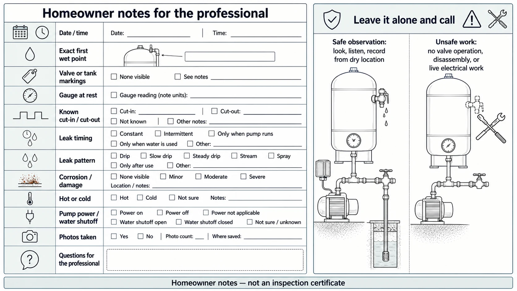
The best service call starts with the smallest safe evidence set. Do not try to prove the failed part. Give the professional enough context to avoid a blind replacement and to recognize a possible over-pressure event.
Record these details
- Exact wet point: relief outlet, valve body, threaded connection, tank seam, gauge port, drain, Schrader stem, or water-heater discharge tube.
- Whether the first bead appeared at the top, side, bottom, or downstream end of the visible assembly.
- Tank brand, model, serial or date code, maximum working pressure, and any relief-valve marking visible without removing anything.
- Gauge readings at rest, pump start, and pump stop, if those events occurred normally and were safe to observe.
- The known cut-in/cut-out range and where that information came from; mark it as “known,” “label,” “service record,” or “unknown.”
- Whether the pump stopped, ran continuously, short-cycled, or could not be safely observed.
- Whether the leak began at rest, during pressure rise, near pump stop, after a fixture opened, or after a hot-water event.
- Leak pattern: dry, bead, intermittent drip, steady drip, stream, spray, or unknown.
- Corrosion, bulging, cracked fittings, damaged discharge piping, missing caps, blocked outlets, or water near electricity.
- Recent work: tank, pump, pressure-switch, plumbing, filter, softener, water-heater, well, or electrical service.
- Photos taken from a dry, safe location, including the whole assembly and the label; never remove a cover to make the photo better.
Tell the caller plainly: “This may be a pressure relief valve at a private-well tank, but I have not operated or isolated it.” Include the pressure sequence and whether pump power was shut off. Ask whether the company wants the system left off, whether a plumber or well contractor should attend first, and what information they need before arrival. If your water supply is interrupted, ask about temporary drinking-water arrangements rather than bypassing the safety device.
7. What the repair decision should cover
A professional diagnosis should distinguish at least four questions:
- Is the wet component the correct relief device? Verify the valve's location, outlet, marking, and connection to the protected tank or piping.
- Did the valve open because pressure rose? Compare the gauge, known pump cycle, pressure-switch operation, pump capacity, blocked piping or filtration, and the tank's rated pressure. A valve that opened correctly may need an over-pressure cause corrected, not just a valve replacement.
- Is the valve leaking below its expected setting? Check the valve, seat, debris, gauge accuracy, connection, rating, and installation. Do not infer from a single gauge reading that the valve is defective.
- Is the tank or piping compromised? Check for corrosion, loss of precharge, waterlogged or failed tank components, damaged threads, and prior modifications. AMTROL warns that loss of air, reduced pump-cycle time, or visible corrosion changes the precharge decision; it specifically warns against adding pressure to a compromised tank.
The professional should also verify that any replacement relief valve is compatible with the tank, pump, piping, water chemistry, and local requirements; that the discharge can safely drain; and that no shutoff or obstruction defeats the protection. If the well pump or control system is implicated, the repair scope may include electrical testing, pressure-switch service, pump-flow evaluation, or a tank assessment. Those are not homeowner tests.
Do not confuse a water-heater diagnosis with a well-tank diagnosis
A. O. Smith's technical bulletin on leaking T&P valves separates a leak at the water-heater tank connection, a leak at the threaded valve connection, intermittent pressure or thermal-expansion weeping, and a large hot-water discharge associated with temperature. That branch belongs to a water-heater professional and its exact manual. It should not be used to diagnose a cold-water well-tank relief valve, and a well-tank relief valve should not be selected or repaired using water-heater T&P assumptions.
8. After repair: preserve the safety evidence
Ask for the cause and the corrected operating range in writing. Keep the tank and pump model, pressure-switch setting, relief-valve marking, service date, and any photos with your well records. The useful closeout record says whether the valve was leaking at its seat or connection, whether an over-pressure condition was found, whether the pump stopped at the intended cut-out, whether the tank showed corrosion or air-loss evidence, and what future observation would require another shutdown.
Do not treat a dry valve after replacement as proof that the system is safe forever. Manufacturer instructions differ by tank family, and local installation requirements differ by jurisdiction. Pentair's FAQ gives a 4-psi-below-cut-in air-cell figure for its WellMate equipment after the tank is drained and power is off, while AMTROL gives a 2-psi-below-cut-in procedure for its precharged tanks. Those differences are exactly why a homeowner should not apply a generic precharge number or use a compressor to chase a leak.
At your next qualified service visit, ask whether the tank, gauge, relief valve, pressure switch, discharge route, and pump controls are still a matched system. Have the professional note any local code or permit requirement that applies to the installation. The homeowner decision is complete when the wet component is identified, the pressure-and-timing record is preserved, the relief path remains unobstructed, and any abnormal pressure or damaged equipment is in qualified hands—not when the drip is merely hidden.
Sources and scope
Evidence behind this page
- AMTROL — Precharged Well Tanks Installation, Operation & Maintenance Instructions
AMTROL precharged well tanks identified in the manual; use the actual tank and relief-valve documentation for any other model or installation.
- AMTROL — Precharged Well Tanks Installation, Operation & Maintenance Instructions
AMTROL installation and safety guidance; the page uses this as a model-neutral identification clue, not a substitute for the installation drawing.
- AMTROL — Precharged Well Tanks Installation, Operation & Maintenance Instructions
AMTROL safety warnings for its precharged well tanks; this supports a conservative homeowner boundary and does not declare every tank installation identical.
- Pentair WellMate FAQs
Pentair WellMate equipment FAQ; the valve-stem location supports distinguishing the Schrader air valve from a relief-valve discharge.
- Pentair WellMate UT, HP & SP Series Installation Instructions
Pentair WellMate UT, HP, and SP series installation instructions; the no-isolation rule is not generalized here to local code beyond the cited product guidance.
- Washington State Department of Health — Pressure Relief Valves on Pressure Tanks
Washington drinking-water technical guidance and Washington-specific requirements; it is used for the safety principle and explicitly not presented as a national code rule.
- Penn State Extension — Using Low-Yielding Wells
Penn State Extension's low-yielding-well example; actual cut-in and cut-out settings vary by installation and must be read from the system documentation or observed by a qualified professional.
- A. O. Smith — GCV-30 Instruction Manual
A. O. Smith storage water-heater manual; this distinguishes a hot-water T&P valve from a cold-water well pressure-tank relief valve and is not a claim about every water heater model.
- A. O. Smith — Technical Bulletin 52: Leaking Temperature and Pressure Relief Valve
A. O. Smith water-heater bulletin; its failure branches are not transferred to a cold-water well-tank relief valve.
- Merrill Manufacturing — Pressure Relief Valves Guide
Merrill cold-water well-system relief-valve guide; used only for possible causes and product-context examples, not for diagnosing another brand or installation.
- CDC — Well Water Safety
CDC public-health guidance for private wells; this supports a conservative drinking-water boundary and does not identify the source of a particular leak.