Well Pressure Gauge Not Working: Read the Evidence Before Replacing Parts
A safe homeowner decision surface for a stuck, drifting, or misleading well pressure gauge, with readings, pump behavior, and clear stop points.
The short answer
A well pressure gauge can fail, stick, or lose its sensing path without proving that the pump, switch, or tank has failed. From a safe location, record the gauge at rest, pump start, pump stop, water flow, and timing. A hose-bib gauge is only a comparison clue. Do not adjust a pressure switch, recharge a tank, open controls, or run a pump against a closed outlet; hand the record to a qualified well professional.The shortest safe answer: a well pressure gauge is an instrument, not a diagnosis. A stuck needle, a zero reading, or a gauge that does not rise while the pump runs can mean the gauge has failed or its small pressure connection is restricted. It can also reflect a real system problem: a leak, low well yield, a blocked or worn pump, a check-valve problem, control trouble, or a tank and switch relationship that is no longer behaving normally. The reading alone cannot choose which part to replace.
From a safe location, record the gauge reading, what the pump is doing, whether water is actually flowing, and how long the change takes. Do not open a pressure-switch cover, touch wiring, remove the gauge, recharge the tank, operate a relief device, run a pump against a closed outlet, open the well, pull a pump, or enter a pit or confined space. Pentair warns of hazardous voltage around the motor and pressure switch, and Amtrol warns that tank pre-charge work can create rupture or explosion hazards. Those are qualified-professional tasks, not the next step in a homeowner gauge check.
Treat the gauge as one piece of evidence
A typical private-well pressure system has a pump, discharge piping, pressure tank, pressure switch, gauge, relief device, and household plumbing. The gauge may be mounted at a tank tee or pump connection, while the pressure switch may sense pressure through its own connection. The point is important: the dial shows what reaches that instrument at that moment. It does not directly show pump output, well yield, tank condition, switch contacts, or pressure at every fixture.
The tank and switch are related, but they are not the same component. In Pentair's description, water entering a pre-charged tank compresses the air around the water cell; the cycle ends when the compressed air reaches the switch's cut-off setting. Pentair's pressure-tank manual describes that operating relationship. A switch decides when the pump starts and stops; a gauge reports pressure. A disagreement between those pieces is a reason to collect better evidence, not permission to adjust the switch.
The small connection behind a gauge can also be part of the uncertainty. Pentair's Simer pump manual shows gauge placement at the pump body or a priming tee depending on configuration and warns that an air leak in suction piping prevents the pump from pulling water from the well. A model-specific Wayne jet-pump manual lists clogged air-volume-control tubing, well-side restrictions, clogged screens or nozzles, and other blockages as possible causes of pump-system symptoms. That does not prove that your gauge port is blocked, but it supports keeping the sensing path and nearby fittings in the professional's differential diagnosis. Mineral scale, sediment, rust, sealant debris, or corrosion can be plausible site-specific explanations; only an appropriately isolated and depressurized inspection can establish one.
The practical boundary is this:
| What you see | What it can support | What it cannot establish | Safest next step |
|---|---|---|---|
| Needle stays at one number while the home still has changing flow or pump cycles | The dial or its sensing path may be unresponsive | That the pump, switch, or tank has failed | Record the comparison between flow and dial movement; request a gauge-and-port check |
| Needle moves slowly, jumps, or drifts after a fixture closes | A real pressure change, a leak, check-valve behavior, or instrument error is possible | Which component is responsible | Repeat one controlled observation and record timing; escalate if pressure does not stabilize |
| Gauge is non-zero with fixtures closed | There may be trapped or normal system pressure, or the gauge may be offset | That water is available at the fixture or that the pump is healthy | Read the faucet flow and gauge together; do not bleed pressure from a fitting |
| Pump runs and gauge does not rise | No pressure is reaching the instrument, or the system is not building pressure | That the pump is dead | Stop prolonged running, record flow and sound, and arrange professional diagnosis |
| Gauge and a hose-bib gauge disagree | The two locations or instruments are seeing different conditions | Which gauge is correct or why they differ | Take simultaneous, labeled readings and give both to the professional |
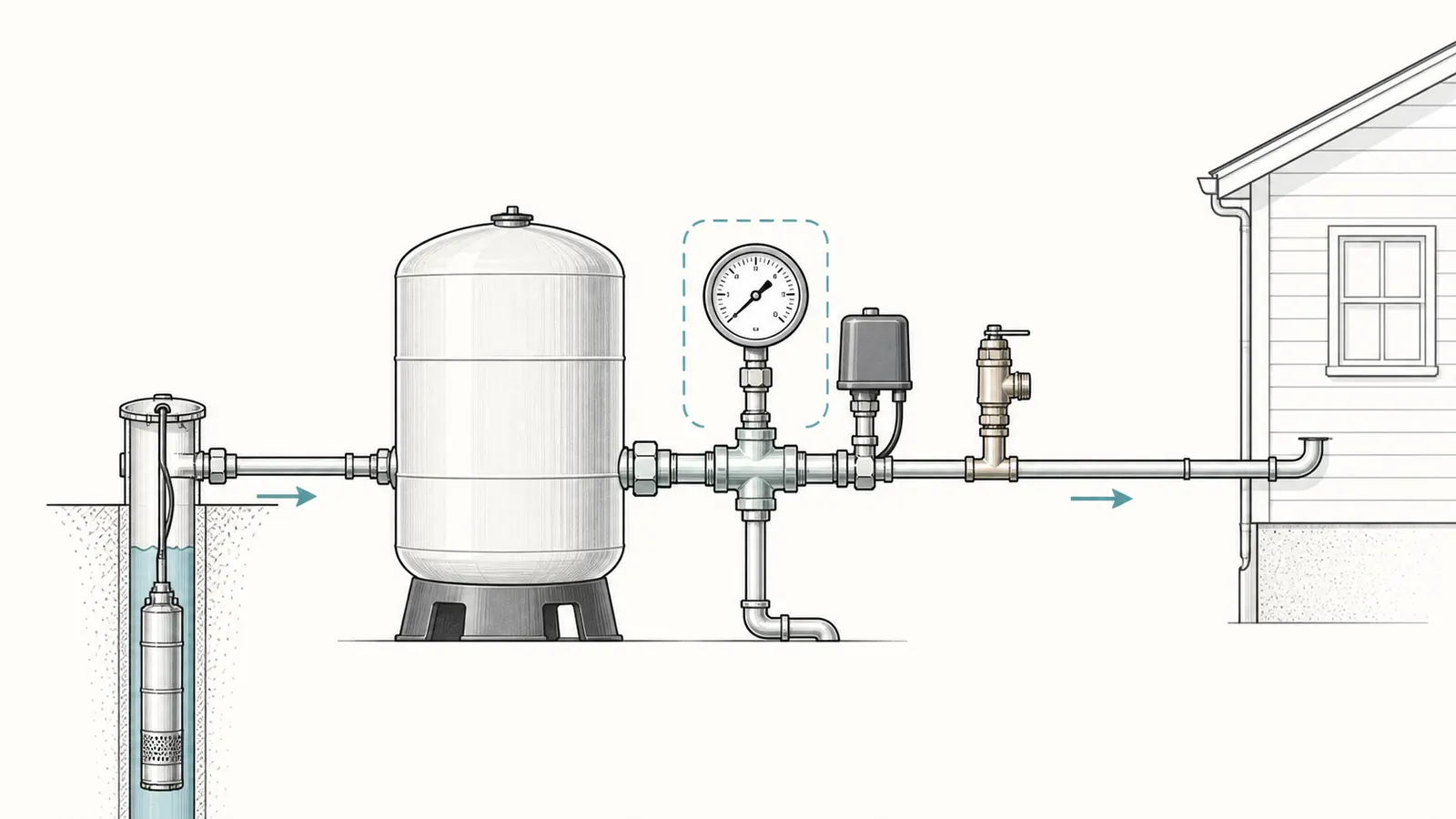
This is an evidence boundary, not a list of homeowner repairs. A pressure gauge that lies can cause an expensive cascade: a switch gets adjusted to match a bad dial, a tank gets recharged to the wrong number, or a pump gets replaced even though the restriction is at the instrument connection. The first decision is whether the reading is trustworthy enough to use.
Establish the system's known baseline
Before interpreting a new symptom, collect the records that give the numbers meaning. The Water Systems Council's well inspection guide calls for recording pump cut-in, cut-out, differential, and the time from cut-in to cut-out with no water running in the home. Its record guidance also emphasizes keeping the well log, maintenance history, and water-test results. NGWA's wellowner.org maintenance guidance similarly points owners to well logs and pump-installation records when troubleshooting future issues.
Look for:
- the well log or drilling report, including original depth, static water level, pump setting, and reported yield;
- the pump make, model, horsepower, voltage, and installation date, if known;
- the pressure tank make, model, maximum working pressure, and approximate age;
- the written cut-in and cut-out settings, such as 30/50 or 40/60, if they are documented;
- dates of pump, tank, switch, gauge, treatment, plumbing, or well work;
- any recent flooding, drought, power interruption, freezing, construction, or water-quality change;
- whether the symptom affects every fixture or only one faucet, shower, appliance, or treatment branch;
- whether a relief valve has discharged, a pipe is leaking, a breaker has tripped, or the pump has been cycling unusually.
Do not fill in missing numbers from a familiar pattern. A 30/50 system is common, but “common” is not a verified setting for this property. Pentair's switch instructions describe a typical 20-PSI start/stop differential and say the switch should not be adjusted to cut on below 20 PSI or cut off above 60 PSI for the covered instruction set. That is a manufacturer instruction for the relevant switch family, not a national rule and not a reason to change your setting. Read the exact switch manual before anyone evaluates a control.
The tank pre-charge is another number that is easy to misuse. Pentair's procedure says to turn off pump power, drain the tank completely, and then check air pressure; for its pre-charged tank instructions, the target is 2 PSI below cut-in. That number applies only within the manufacturer's procedure and compatible tank design. It is not the water pressure on the dial, and it is not a setting to guess while the tank remains pressurized. Amtrol's Well-X-Trol manual is more restrictive for its product: it warns against adding pressure where corrosion or damage exists and says only licensed professionals should check, adjust, or recharge tank pre-charge.
If the baseline is missing, the useful deliverable is not a new setting. It is a dated observation record that tells the service professional what the system did before anyone changed it.
Read the four misleading-gauge patterns
A stuck or zero needle
If the needle stays at zero while a fixture supplies water, the dial may be wrong, but do not assume zero pressure merely because the dial says zero. If the pump starts and the home receives water, the system has at least some pressure-producing path somewhere. The gauge may be failed, its connection may be restricted, or the gauge may be located on an isolated side of a valve or fitting. If the home has no water, zero may be accurate; the absence of water then makes the system-level branches more important, including power, pump operation, a leak, a check valve, a low water level, or a blocked intake.
Observe whether the needle moves when the pump audibly starts or stops. One unchanged needle is not enough to separate a dead gauge from a restriction. A needle that remains exactly fixed during a clearly visible change in water delivery should be labeled “untrusted,” not converted into a pump verdict.
A drifting, jumping, or sluggish needle
A slow fall after a fixture closes can be a real pressure loss through a leak or check-valve path, but it can also be a gauge that responds slowly. A needle that jumps when the pump starts may reflect real pressure pulsation, vibration, a loose or damaged instrument, or a sensing connection that is not transmitting pressure cleanly. The meaningful detail is the sequence: did the pump start, did water flow, did the gauge move, and did it return after the fixture closed?
Record the direction and timing rather than trying to stabilize the pointer. “Falls 10 PSI in 40 seconds with all fixtures closed” is useful. “Gauge seems bad” is not yet a service-ready observation. If the pressure falls while nobody is using water, check visually for accessible leaks and listen for water movement, but do not dismantle plumbing or open a buried or pressurized connection. A concealed leak, failed check valve, or treatment-device flow path requires professional isolation and testing.
A non-zero reading with no fixture running
A non-zero reading at rest is not automatically abnormal. A pressure tank system is designed to hold water pressure between pump cycles, so a gauge can remain above zero while fixtures are closed. The question is whether the value is plausible for the documented system and whether it changes when a normal fixture is opened.
Do not interpret a non-zero dial as proof that water should flow. A closed valve, frozen line, clogged filter, failed pressure-reducing device, or local plumbing restriction can leave pressure at one point while a downstream fixture has little or no flow. Conversely, a gauge can show a number even when its pointer is not tracking the pressure accurately. The safe comparison is “gauge reading plus actual flow plus pump behavior,” not the number in isolation.
If the gauge is high, the pump runs continuously, or a relief device is discharging, stop using water and arrange prompt professional help. Do not test the system by closing the discharge and watching how high the dial climbs. Pentair explicitly warns not to run a pump with a closed discharge longer than needed to read dead-head pressure because of explosion risk. A homeowner does not need that test to document the symptom.
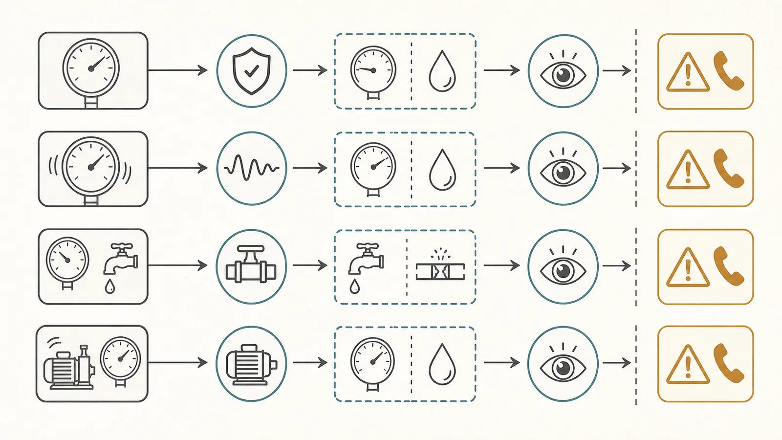
The pump runs but the gauge does not rise
This is the most dangerous branch for false confidence. A pump that runs without a gauge rise may be failing to move water, may be unable to reach the expected pressure, or may be moving water through a leak or open path. It may also be producing pressure that the gauge cannot see because the instrument or sensing connection is wrong. Wayne's troubleshooting chart lists low supply voltage, well-side leaks, clogged screens or nozzles, low water level, incorrect or undersized pump components, and cavitation among causes of little or no water for its jet-pump series. It lists a separate group for frequent cycling, including tank, piping, valve, pre-charge, and switch conditions.
The homeowner-safe observation is limited: note whether water is coming from the open fixture, whether the pump sound is steady or changes, whether the gauge moves at all, and whether the pump stops on its own. Do not run the pump for an extended period to “see if it catches up.” If it does not stop, or if flow is absent while the motor runs, stop the observation and call. If the clearly identified pump disconnect can be reached without opening a control box or crossing water, a professional may tell you to turn it off; do not guess at an unidentified breaker or touch live equipment.
Run a safe observation from the outside of the system
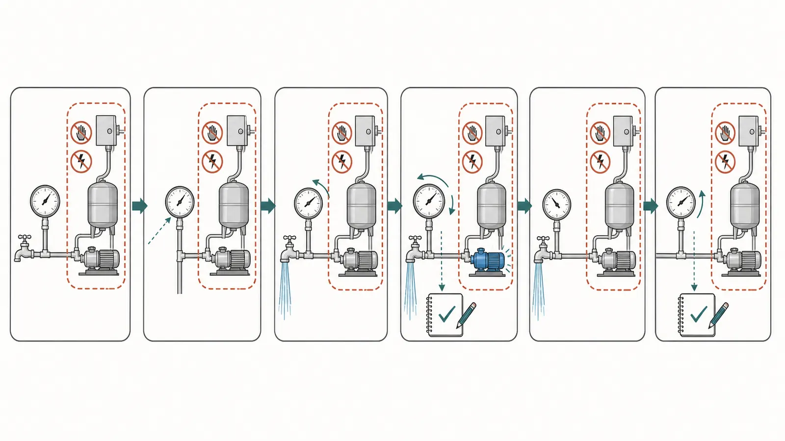
This procedure is for a homeowner who can see the gauge and observe a normal fixture without entering a pit, opening a panel, removing a cover, or touching the equipment. Have a second adult read the gauge if the fixture and gauge cannot be seen together. Do not create a special test by closing valves or covering relief devices.
- Make the area safe. Keep away from standing water, exposed conductors, damaged insulation, hissing or spraying connections, a leaking tank, or an active relief-valve discharge. If any are present, stop and call a qualified professional. Do not open a well cap or enter a well house, pit, crawlspace, or other confined space.
- Freeze the starting conditions. Turn off normal water use: faucets, showers, toilets, ice makers, irrigation, water softeners, filters with automatic regeneration, and appliances that may be filling. Do not disconnect or bypass equipment to make this easier. Record the date, time, weather or recent event, and which fixtures were closed.
- Read without touching. From a dry, safe position, photograph or write down the gauge value and pointer position. Note whether the dial is fogged, cracked, bent, corroded, or visibly damaged. Do not tap the glass or housing. A pointer that moves after tapping is not calibrated by the tapping; it is a reason to distrust the instrument.
- Open one ordinary cold-water fixture. Use a fixture that normally has unrestricted flow and is not downstream of a special treatment device if possible. Open it gradually and keep the fixture under control. Record the initial flow: normal, weak, pulsing, air-spurting, or absent.
- Record the sequence. Write down the gauge reading before flow, when the pump starts if it is audible or visible from a safe location, the reading while water flows, and whether the pump stops. Do not open the pressure-switch cover to watch contacts and do not test voltage. If the pump runs continuously or the gauge does not rise, end the observation.
- Close the fixture once. Record whether the needle returns, freezes, drifts, or overshoots. Note the time from pump start to pump stop only if the pump completes a normal cycle without intervention. The WSC guide specifically treats the cut-in-to-cut-out time with no water running as useful baseline information; it is not a command to force a cycle.
- Repeat only once if conditions remain safe. A single repeat can show whether the pattern is reproducible. Repeatedly starting a pump to chase a reading can create short cycling and heat. Do not continue if water is leaking, the motor sounds distressed, the pump will not stop, or the pressure appears excessive.
Use a record like this:
| Date/time | Fixtures closed | Gauge before flow | Fixture flow | Pump start | Gauge during flow | Pump stop | Time to stop | Gauge after close | Notes |
|---|---|---|---|---|---|---|---|---|---|
| 2026-08-24 08:15 | All except kitchen cold faucet | 42 PSI | Normal | 08:16:10 | 35 PSI, no visible rise after start | 08:16:48 | 38 sec | 49 PSI, then steady | No leaks seen |
The numbers in the example are a format, not a normal target and not a test result. Replace them with your observations. If you do not know the gauge units, write down exactly what the dial shows instead of converting it.
Use a hose-bib gauge only as a timed comparison
A temporary hose-bib gauge can answer a narrow question: what pressure is present at that faucet at that time? EPA WaterSense describes attaching a pressure gauge to a hose bibb or cold-water faucet and opening the water fully to verify service pressure at that location. That EPA method is useful for a comparison reading, but it does not certify the tank-side gauge.
If you use one, treat it as a second observation:
- Use a gauge with a range that safely covers the expected system pressure and a connection that fits without force. Do not modify piping to install it.
- Choose an accessible cold-water hose bibb or faucet. Do not use a damaged, leaking, frozen, hot-water, or chemically treated connection.
- Close normal fixtures and write down the tank-side gauge and hose-bib gauge at the same time, including the exact locations.
- Open the selected faucet fully only if the fixture and hose connection are sound. Record both readings while water flows and again after closing it.
- Record anything between the tank-side gauge and the hose bibb: filters, softeners, treatment units, regulators, check valves, long pipe runs, or elevation changes.
The two readings may differ because they are in different locations, not synchronized, or separated by equipment and pipe friction. A hose-bib gauge can also be wrong, poorly connected, damaged, or affected by a restricted faucet. Agreement increases confidence that the pressure change was observed at both points; disagreement identifies a question for the professional. It does not prove that the tank-side dial is bad, that the hose-bib gauge is right, or that a pump or tank should be replaced.
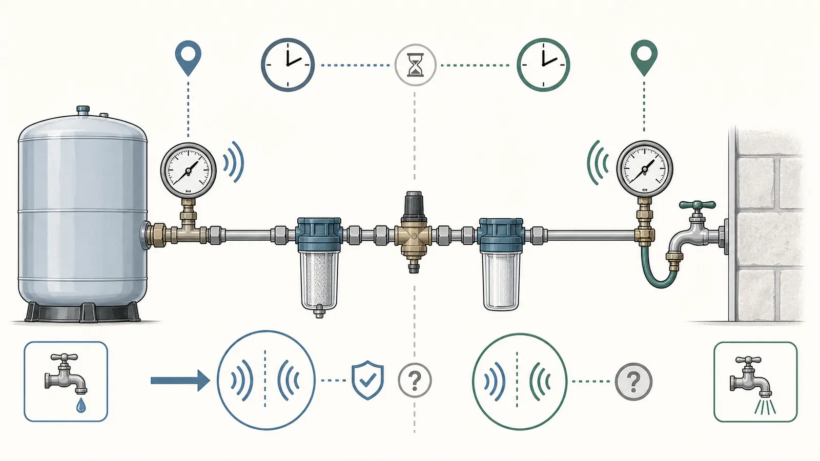
Do not remove the installed gauge to make the comparison. Do not loosen a tank-tee fitting, clear a port with a wire, bleed water from a connection, or install a gauge on a pressurized line unless the work is performed by a qualified person under the equipment's instructions. The pressure-switch and tank manuals make clear that isolation, power status, pressure release, and equipment integrity matter before service begins.
Know when the observation must stop
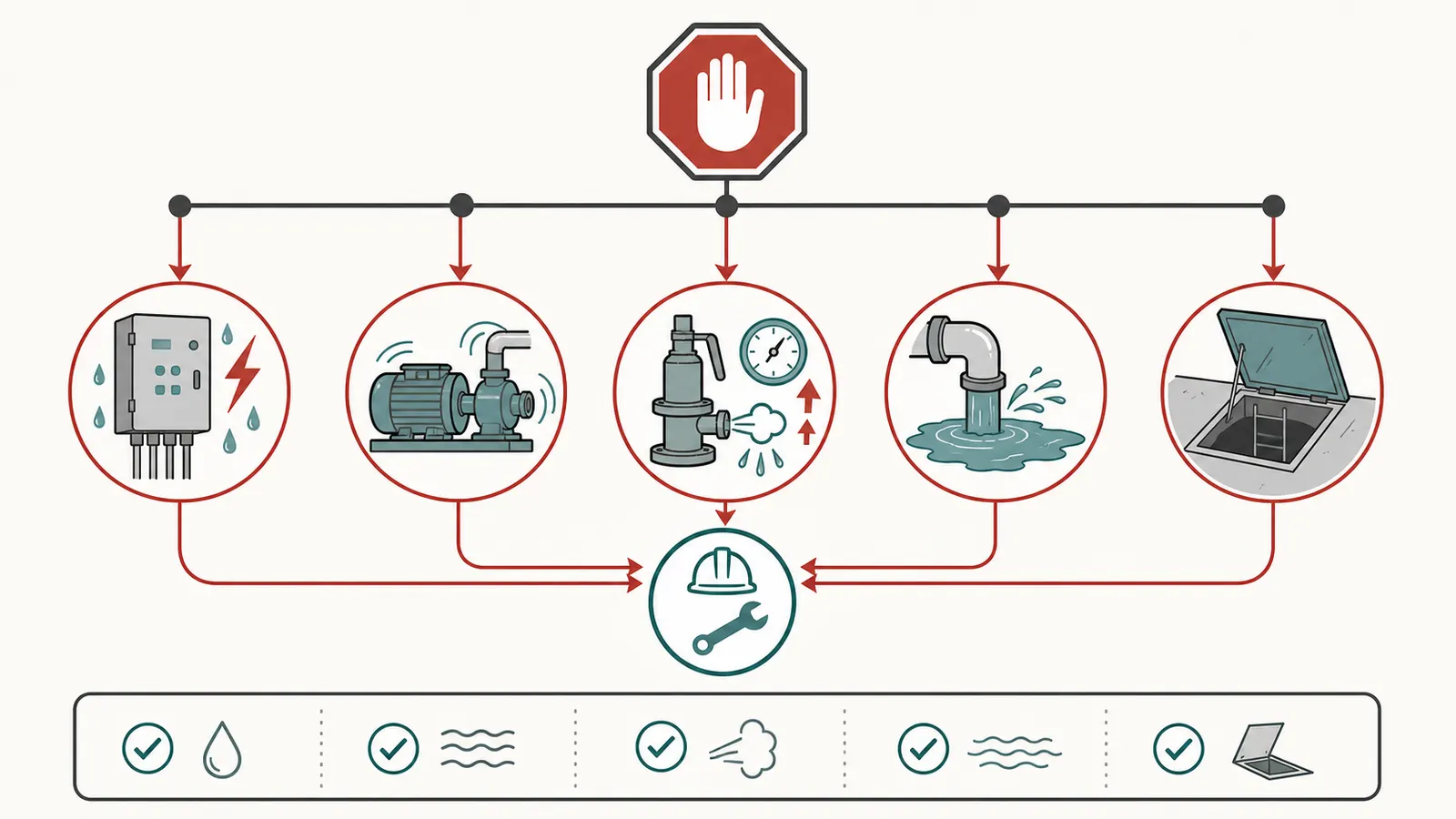
The following conditions change the task from information gathering to hazard control. Stop observing and contact a qualified well-system professional, licensed electrician, or emergency service as appropriate to the condition:
Rules about licensing, permits, and who may service a private well vary by state and local jurisdiction. If you are unsure who is authorized or whether a permit is required, pause and confirm the applicable requirements with your state or local well, health, or building authority before scheduling component work; EPA's private-well guidance directs owners to state or local agencies and qualified water-system professionals.
- Live-voltage uncertainty: an exposed control, open pressure-switch cover, wet electrical box, damaged cable, buzzing, arcing, burning smell, or a breaker that trips again. Never test live wiring, reach into a control box, or assume a breaker has made the equipment safe.
- Pump will not stop: a pump that continues running with a normal fixture closed can overheat or indicate a control, leak, water-level, pump-output, or pressure-sensing problem. Do not keep waiting for the dial to climb and do not close the discharge to force a stop.
- Relief-valve activity or suspected overpressure: water from a relief discharge, a gauge near or above the equipment rating, a damaged or corroded tank, bulging, unusual vibration, or a sudden pressure event. Keep clear; do not cap, plug, adjust, or hold the relief device shut.
- Active water leak or flooding: water near electrical equipment, a spraying connection, a tank seam leak, or water entering the building. Protect people and property only if you can do so without contact with energized equipment or pressurized parts.
- Need to open the system: removing the gauge, opening the tank air valve, draining the tank, adjusting the pressure switch, clearing a sensing port, changing a relief valve, or separating piping. These are not needed to make the first evidence record.
- Need to access the well: opening the well cap, pulling a pump, lowering a tool, entering a pit, or entering a confined space. NGWA warns that self-servicing can lead to injury, damage, electrocution, and confined-space or gas hazards; the WSC guide assigns detailed component inspection to a licensed well contractor.
If a water-quality concern accompanies the pressure symptom—cloudiness after a well event, flooding, a damaged cap, or a change in taste or odor—treat that as a separate safety track. EPA's private-well guidance says well construction and location affect drinking-water safety, and EPA's testing and treatment guidance recommends certified laboratories and notes that some conditions may require a new water source or well rather than on-site treatment alone. A pressure gauge cannot establish potability.
Hand over a service-ready evidence packet
The best outcome of a homeowner check is a concise record that lets the professional begin with the right questions. Send or bring:
- The symptom in one sentence: for example, “The dial stayed at 38 PSI while the kitchen faucet flow went weak and the pump continued for 90 seconds.”
- The observation table: include dates, fixture state, gauge readings, pump start and stop, cycle time, flow description, and what happened after closing the fixture.
- A photo set from safe positions: the full tank-and-pump area, the gauge face, the equipment labels, visible piping, relief-valve discharge route, and any visible leak or corrosion. Do not remove covers for photographs.
- System identity: well type if known, pump and tank models, switch setting if documented, gauge range, treatment equipment, and approximate installation dates.
- History: recent repairs, power events, freezing, drought, flooding, construction, water-quality work, and changes in household demand or irrigation.
- The comparison conditions: whether the home had water, whether the hose-bib gauge was used, the exact location of each reading, and any filters, regulators, or valves between them.
- The decision boundary: explicitly say what you did not do: no switch adjustment, no live-voltage test, no tank recharge, no gauge removal, no well access, and no closed-discharge test.
Ask the professional to state which measurement will distinguish the main branches before replacing a component. A properly scoped visit may need to verify the gauge against a known instrument, inspect the pressure-sensing connection, check switch operation with appropriate electrical safety, evaluate tank condition and pre-charge under the manufacturer's procedure, assess leaks and check-valve behavior, and compare pump performance with well conditions. The exact tests depend on the pump type and installation; a homeowner should not select them by trial and error.
The well's yield is another reason not to jump from “no rise” to “bad pump.” The WSC guide says a flow test is a snapshot and does not represent long-term recovery; a true yield test involves static level, drawdown, and recovery and should be performed by a licensed well contractor. A low-yield well, a dry-running risk, or a seasonal water-level change can look like a pump or gauge problem during a short observation.
Finally, ask for the diagnosis in evidence terms: which readings were trusted, which instrument was verified, where pressure was measured, what happened under flow, whether the pump reached and held its documented cut-out, whether the tank and switch relationship was checked, and what assumption supports any replacement recommendation. If the answer is only “the gauge says zero, so replace the pump,” the evidence surface is incomplete.
The decision is therefore simple even when the system is not: preserve the original readings, test the meaning of the gauge before trusting it, observe only from a safe location, and escalate component work to a qualified well professional. A misleading dial is a reason to improve the evidence trail—not a reason to adjust a switch or buy a pump on speculation.
Sources and scope
Evidence behind this page
- Pro-Source Steel Pressure Tanks Manual
Pentair Pro-Source tank operating explanation; the exact tank, switch, and installation determine the actual system behavior.
- Pro-Source Steel Pressure Tanks Manual
Pentair Pro-Source installation and service procedure; not a homeowner authorization to open or service a pressurized tank.
- Adjusting Well Pump Pressure Switches Instructions
Pentair Parts2O pressure-switch instructions; electrical work and switch adjustment are not homeowner observation steps.
- Adjusting Well Pump Pressure Switches Instructions
Pentair pressure-switch instructions; this is a prohibition on a homeowner pressure test, not a universal system pressure limit.
- Well-X-Trol Installation and Operation Manual
Amtrol Well-X-Trol tank safety instructions; the manual applies to that product line and reinforces the safety boundary for pressurized tanks.
- wellcare Information for Home Inspectors: Guide to Evaluating Water Wells
Water Systems Council homeowner and inspection record guidance; existing state or local requirements control where they differ.
- wellcare Information for Home Inspectors: Guide to Evaluating Water Wells
Water Systems Council inspection guidance; licensing and authorization are jurisdiction-specific.
- wellcare Information for Home Inspectors: Guide to Evaluating Water Wells
Water Systems Council well-capacity guidance; it does not diagnose the cause of a particular pressure symptom.
- Well Owner Routine Maintenance Practices
National Ground Water Association homeowner guidance; frequency and licensing details can be supplemented by state requirements.
- Learn About Private Water Wells
U.S. EPA private-well overview; local licensing, construction, and code requirements vary.
- WaterSense Labeled Homes Technical Sheet: Service Water Pressure
EPA WaterSense service-pressure verification method; it is not a calibration procedure for a well-system gauge and local plumbing arrangements vary.
- CWS Series Convertible Well Jet Pump Operating Instructions and Parts Manual
Wayne CWS-series model troubleshooting; the listed branches are examples of system-level possibilities, not a diagnosis for every well.
- Simer Shallow Well Convertible Jet Pump and Tank Owner's Manual
Pentair Simer pump configurations; gauge location and suction-piping details vary by pump type and installation.