Do You Need to Replace the Pressure Tank With a Well Pump?
A homeowner worksheet for deciding whether to retain, retest, replace, or upsize a pressure tank when a well pump is replaced.
The short answer
Not automatically. Retain the tank only when its type, shell, pressure and temperature ratings, precharge, drawdown, controls, and the replacement pump’s delivery at system head are verified. Replace or upsize it when condition, usable drawdown, run time, or safety hardware cannot be demonstrated. Stop for a qualified review when the pump curve, controls, or pressure rating is unknown.Observation flow
What is the system doing?
Choose the closest visible pattern. Stop immediately for sparking, hot wiring, uncontrolled pressure, or a damaged tank.
Do I Need to Replace My Pressure Tank When Replacing My Well Pump?
Not automatically. A new well pump can work with an existing pressure tank when the tank is sound, its pressure and temperature ratings cover the system, its usable drawdown is enough for the replacement pump and controls, and the connections and safety devices remain appropriate. A tank that is merely “the same age as the pump” is not automatically bad; a tank that looks clean is not automatically compatible.
The defensible decision is to document six things before approving the scope:
- What tank type and model are installed, and is the shell or vessel visibly compromised?
- Does the tank label cover the system’s maximum pressure and temperature?
- Do the pressure-switch cut-in and cut-out settings match the tank’s precharge and rating?
- What is the tank’s actual or manufacturer-listed drawdown at those settings?
- What flow will the proposed pump deliver at this well system’s total dynamic head?
- Will the tank provide the pump manufacturer’s required minimum run time without rapid cycling, with the existing or proposed controls, check valve, and relief valve?
If all six are documented, retain and retest can be reasonable. If the tank is sound but drawdown is too small, upsize or add tank capacity. If the tank rating, bladder condition, controls, or safety hardware cannot be verified, replace it or stop for a qualified system review. This is a scope decision, not a homeowner invitation to open a pressurized or energized system.
The decision in one page: retain, replace, upsize, or stop
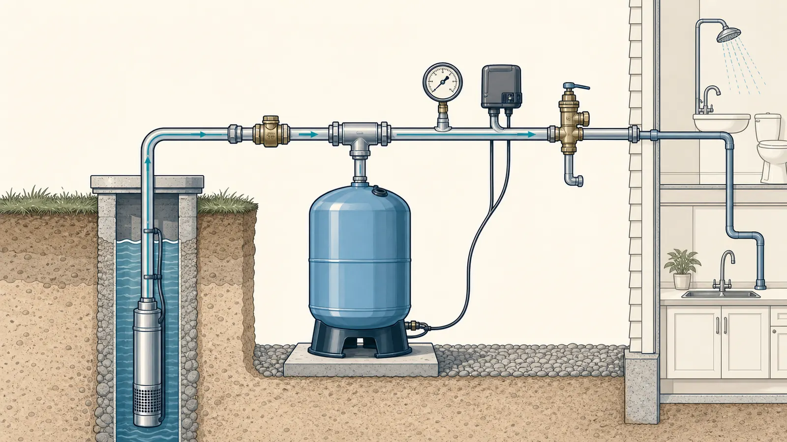
The tank and pump are a coupled system. The tank stores compressed-air energy and usable water between pump cycles; the pump replenishes that drawdown. A pressure switch starts and stops the pump at set pressures. Massachusetts private-well guidance describes the tank’s three practical jobs as maintaining distribution pressure, providing a limited reserve, and reducing pump starts; its example cycle starts near 40 psi and stops near 60 psi. Private Well Guidelines
That means “the pump is new” is not a sufficient reason to buy a new tank, and “the tank still holds pressure” is not a sufficient reason to reuse it. The replacement pump may deliver a different flow, operate against a different head, use a different control strategy, or reach the cut-out pressure much faster. Each change can alter cycle time and the load on the tank and controls.
Use this outcome table with the proposal. A “yes” means the installer has supplied a model-specific record, not just a verbal assurance.
| Gate | Retain and retest | Replace or upsize | Stop for qualified review |
|---|---|---|---|
| Tank identity | Model, type, total capacity, connection and label are legible | Label is missing, unreadable, or a different tank type is proposed without a piping/control plan | Vessel identity or application cannot be established |
| Shell and water-side condition | No visible corrosion, bulging, cracking, leak, freeze damage, or unstable support; professional test is acceptable | Any leak, structural damage, severe corrosion, failed bladder/diaphragm, or waterlogging that returns | Condition cannot be safely inspected or the vessel has been modified |
| Rating | Tank maximum pressure and temperature rating cover the actual system and manufacturer limits | Rating is too low or a replacement control would exceed it | System maximum pressure is unknown or could exceed the label |
| Pressure settings | Cut-in, cut-out, gauge and precharge are documented and consistent with the tank manual | Settings require a different tank or the drawdown becomes inadequate | Switch setting, gauge accuracy, or control type is unknown |
| Drawdown and run time | Listed or measured drawdown meets the required pump flow × minimum run time | Tank is sound but drawdown is short; add capacity or select a larger tank | Pump flow at head or required run time cannot be established |
| Safety and controls | Relief valve, check valve, control box/VFD, wiring and piping remain suitable | Hardware is undersized, missing, damaged, or incompatible | Energized control work, well access, or a code question is involved |
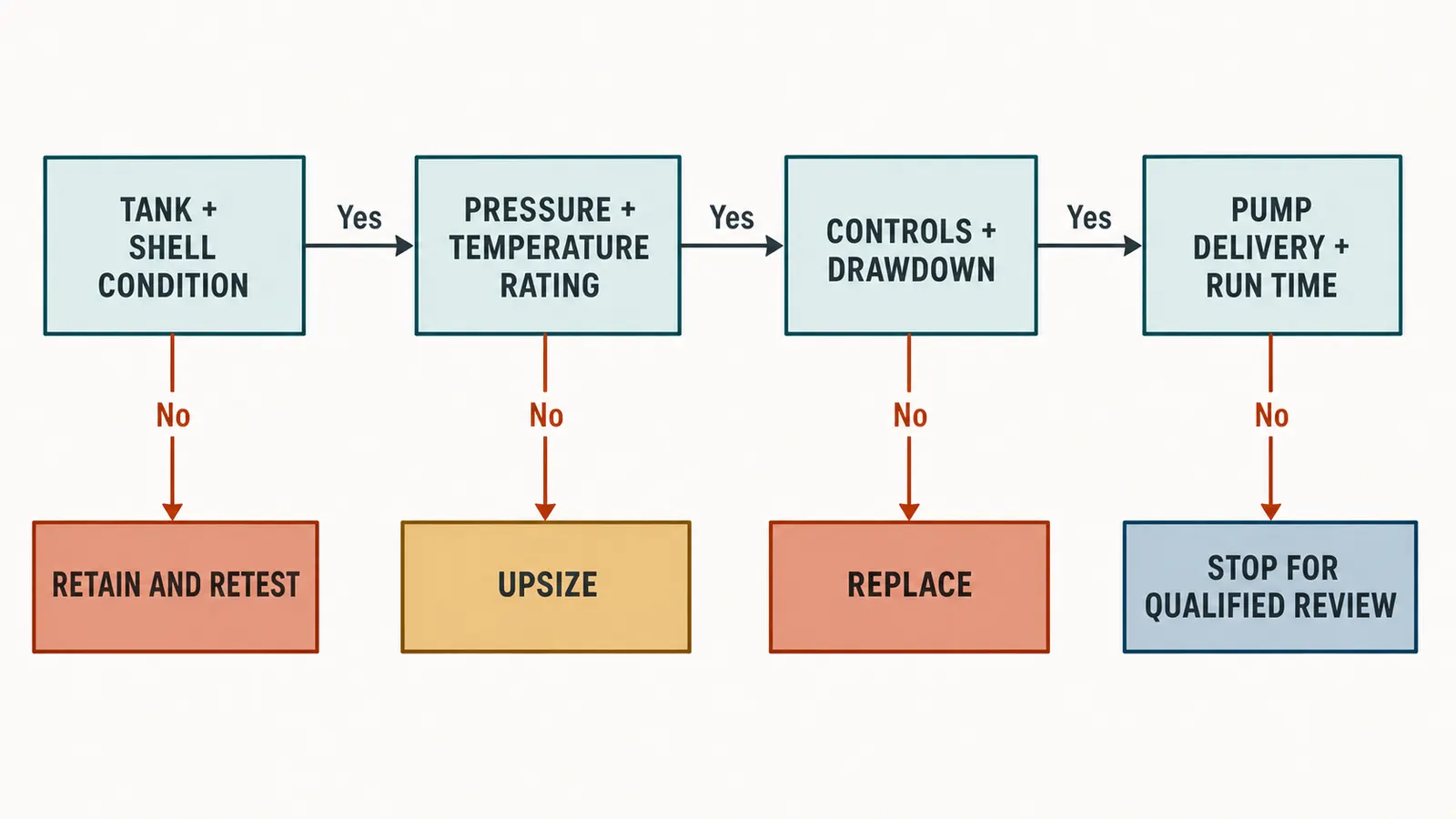
Do not use tank age as a pass/fail gate. Age can justify closer inspection and budgeting, but the evidence above determines compatibility. Conversely, do not let a recent tank purchase override a pressure-rating mismatch or a failed bladder. A pressure vessel’s label and installation instructions govern that vessel.
Gate 1: identify the tank and separate condition from compatibility
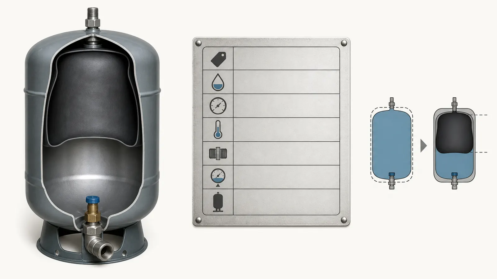
Start with the label, not the invoice. Photograph the entire tank, the label, the pressure gauge, the pressure switch, the pump control box or drive, the relief valve, and the piping around the tank. Record the manufacturer, model, serial or date code if present, total capacity, maximum operating pressure, temperature limits, connection size, orientation, and whether the tank is pre-charged with a bladder or diaphragm or is an air-over-water hydropneumatic design.
This distinction matters. A pre-charged tank uses a bladder or diaphragm to separate compressed air and water. An air-over-water tank uses an air cushion that may require different air-volume equipment and maintenance. A proposal to replace a conventional tank with a pre-charged tank can require a changed tee arrangement and removal or plugging of existing air-charging devices. The Flotec installation manual shows that a pre-charged tank uses one port for both inlet and outlet and directs the pump into a tee serving the tank and house; it also calls out removal of bleeder orifices or other air-charging devices for the applicable submersible installation. Flotec pre-charged tank manual
That is why “the new pump connects to the old tank” is not enough. The system may need to preserve a particular control arrangement, or it may be changing from a standard tank to a pre-charged tank, a constant-pressure system, or a variable-frequency drive. The tank must be evaluated in the arrangement in which it will actually operate.
Safe homeowner observations
You can safely collect evidence from outside the equipment boundary:
- Photograph the tank label and write down every readable number.
- Photograph the gauge while a faucet is closed and while water is being used, without touching the switch or control box.
- Note whether the pump appears to start and stop normally, runs continuously, starts and stops repeatedly during a small draw, or fails to reach the former shutoff pressure.
- Look for water on the floor, staining around fittings, rust-through, a cracked composite shell, bulging, a loose base, damaged insulation, or signs of freezing.
- Record the proposal’s pump model, horsepower, voltage, phase, rated flow, pump curve, control type, intended cut-in and cut-out, and any changes to the check valve or relief valve.
Do not infer bladder condition from a quiet exterior, a single pressure reading, or the absence of a leak. Do not tap the vessel as a “test,” remove a valve core, loosen a fitting, or open a flange. A tank can have a failed bladder without an obvious external leak, and a tank can be mechanically sound yet unsuitable for the proposed pressure range.
What a professional should confirm
Ask the installer to state in writing whether the tank is bladder/diaphragm or air-over-water, what failed or did not fail, and what evidence supports reuse. The requested record should distinguish “tank condition acceptable” from “tank compatible with proposed pump.” Those are different findings.
If the tank is waterlogged, the pump may start too often because very little usable water is available between the switch points. If the shell is damaged, the risk is not merely poor pressure; it is pressure-vessel failure. The manufacturer’s instructions take precedence over a generic rule of thumb.
Gate 2: verify pressure, temperature, and relief protection
Find the tank’s maximum operating pressure and temperature on its label or model documentation. Then compare them with the system’s intended maximum pressure, not merely the current gauge reading. The WellMate WM900 catalog lists capacity, maximum operating pressure, pressure-range-specific drawdown, connection, and temperature limits as separate fields; many listed WM models show a 125 psi maximum operating pressure, with a maximum external operating temperature of 120°F and maximum internal operating temperature of 100°F. WellMate WM900 Composite Pressure Tank Catalog
Those figures are examples for listed WellMate models, not a universal rating. An unidentified tank is an unknown tank. Do not substitute the rating of a proposed replacement for the rating of the existing vessel.
The pressure-switch cut-out must be compatible with the tank’s maximum operating pressure and with the pump’s ability to reach that pressure. A pump that cannot reach cut-out may run continuously. A control setting that exceeds the tank rating is a stop condition. A higher pressure setting can also change drawdown and impose more load on piping, treatment equipment, fixtures, and relief protection.
The relief valve is part of the decision, not an accessory to be checked after the pump is installed. WellMate installation instructions require a pressure-limiting device or pressure relief valve, say the system must not exceed the maximum operating rating on the tank label, and warn that the pressurized tank and connected system must be fully discharged before disassembly. WellMate UT, HP & SP installation instructions The Flotec manual likewise calls for a relief valve near the tank and warns that, for the covered system, pressure must remain below 100 psi; that is a manufacturer requirement for that tank family, not a national rule for every private well. Flotec safety and installation instructions
Temperature is a compatibility check
A tank located in an unconditioned well house, attic, crawlspace, or outbuilding may experience freezing or heat that the tank’s internal or external limits do not cover. The Flotec manual warns that freezing can damage equipment and may lead to tank explosion and serious injury. Flotec safety instructions
For a homeowner, the safe conclusion is simple: record the environment and ask for confirmation. Do not heat a tank with an improvised device, drain it in freezing weather without a system plan, or move a pressurized vessel. If the tank has frozen, shows a freeze split, or has been exposed to a pressure event, stop and obtain a qualified evaluation.
Gate 3: match the pressure switch, precharge, and drawdown
Drawdown is the water actually available from a pressure tank between the pump-off condition and the pump-on condition. It is not the same as the tank’s advertised physical capacity. The Flotec manual explicitly separates tank capacity from drawdown and lists different drawdown values for the same model at 20/40, 30/50, and 40/60 psi. For example, its listed FP7130 has 30.0 gallons of drawdown at 20/40, 26.0 at 30/50, and 22.0 at 40/60. Flotec product table
The same tank can therefore provide less usable water when the pressure range changes. A pump replacement that changes the pressure switch or changes from a fixed-speed pump to a variable-speed control can change the required tank setup. “It is a 44-gallon tank” does not tell you whether it provides enough drawdown.
For the Flotec series, the manual gives these precharge examples:
| Pressure-switch range | Pump starts at | Pump stops at | Listed tank precharge |
|---|---|---|---|
| 20/40 psi | 20 psi | 40 psi | 18 psi |
| 30/50 psi | 30 psi | 50 psi | 28 psi |
| 40/60 psi | 40 psi | 60 psi | 38 psi |
The first number is the pump-on setting and the second is the pump-off setting. These values are for the cited Flotec tank series. The manual says to check or set precharge with no water in the tank and no water pressure in the system. Flotec precharge chart and procedure
That procedure involves isolating electrical power, relieving water pressure, and using the tank’s air valve. It is not a casual homeowner diagnostic. Do not open an energized pressure-switch cover, touch live wiring, remove a valve core, loosen a tank fitting, or manipulate a pressurized tank. Have the qualified installer document the precharge check and the pressure gauge and switch readings.
The drawdown calculation
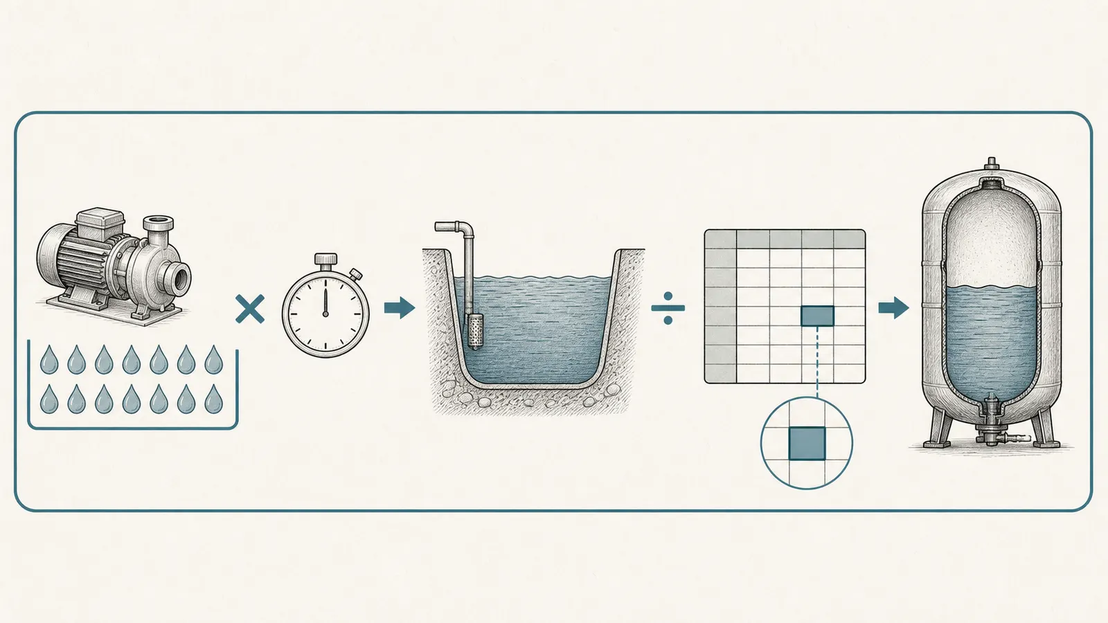
The core sizing relationship is:
required drawdown (gallons)
= pump delivery at the system condition (GPM) × required minimum run time (minutes)

minimum total tank volume
= required drawdown ÷ manufacturer drawdown factor for the actual pressure range
Pentair’s WellMate catalog uses this sequence: enter average pump delivery, enter the required minimum pump running time, multiply them for minimum drawdown, then use the minimum and maximum system pressures to select the drawdown factor and calculate the minimum total tank volume. Its example uses a factor from a specific pressure-range table and warns that actual drawdown varies with system variables such as switch and gauge accuracy and operating temperature. WellMate drawdown sizing procedure
Use the formula only after the installer supplies the two inputs that are often skipped: actual pump delivery at system head and the required minimum run time for the proposed motor/control. Do not use the pump’s catalog maximum flow at zero head. Do not use total tank gallons in place of drawdown. Do not use a factor copied from a different manufacturer’s model table.
A worked example with explicit limits
Suppose the installer documents 12 GPM delivery at the actual operating head and a one-minute minimum run time for the proposed motor. The required drawdown is:
12 GPM × 1 minute = 12 gallons of drawdown
If the actual tank manufacturer’s table gives a 0.30 drawdown factor for the proposed pressure range, the minimum total tank volume would be:
12 gallons ÷ 0.30 = 40 gallons of total tank capacity
This is an illustration of the method, not a recommendation to buy a 40-gallon tank. The factor, pump delivery, run-time requirement, pressure range, tank model, well yield, and control scheme all need to be real values. If the proposal does not show them, the decision is not yet evidenced.
Gate 4: compare the replacement pump at total dynamic head
The pump’s horsepower or a headline “GPM” number cannot establish compatibility. A pump curve relates flow to the head the pump must overcome. Pentek’s selection example adds elevation, friction loss, and required service pressure converted to feet to calculate total dynamic head; it then selects a pump curve that meets that head at the desired flow. The same manual says to compare operating conditions with the pump curve. Pentek pump-selection example
Ask the installer for these values:
| Input | What to record | Why it matters |
|---|---|---|
| Pumping water level | Feet from the reference point, under pumping conditions if available | A deeper pumping level increases lift and can reduce flow |
| Elevation to the pressure gauge or service point | Feet | The pump must lift water to the system |
| Friction loss | Pipe size, length, fittings, filters, treatment equipment and calculated loss | Narrow or obstructed piping consumes head |
| Required service pressure | The intended pressure at the system, often tied to cut-out | Pressure must be converted into head and added to the total |
| Total dynamic head | The installer’s calculated total in feet | This is the operating point to use on the replacement pump curve |
| Pump delivery at that head | GPM from the proposed model’s curve | This is the input for drawdown and cycle-time checks |
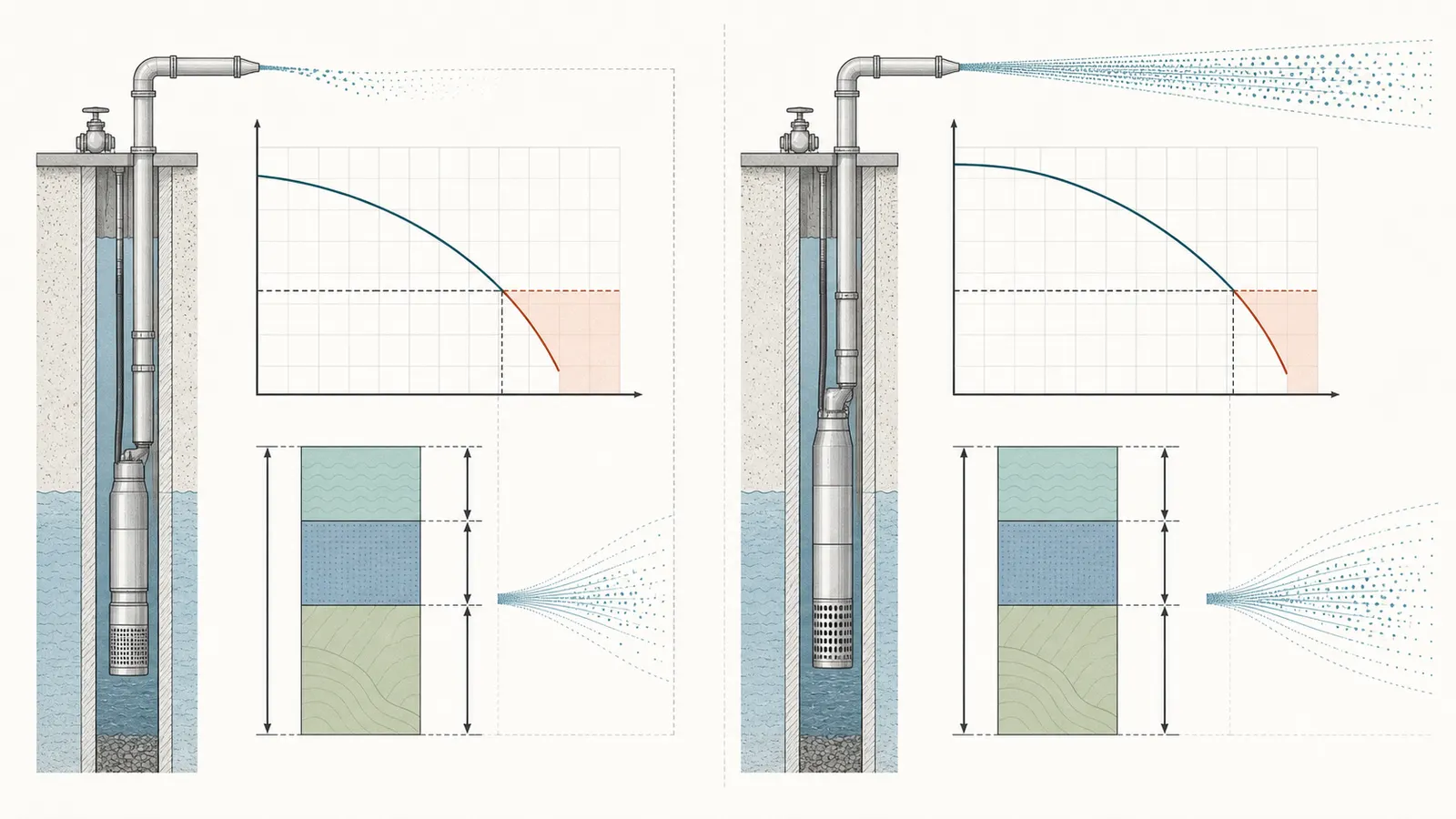
The exact result can differ from the old pump even if the new pump has the same horsepower. A pump that delivers more flow at the same head may fill the tank quickly and cycle too often unless the tank has enough drawdown. A pump that delivers less flow may take longer to reach cut-out or fail to satisfy peak demand. A pump that exceeds the well’s sustainable yield can lower the water level, introduce air or sediment, or run continuously.
The Pentek troubleshooting guidance treats low well level, a worn pump, and a mismatch between operating conditions and the pump curve as separate possibilities. It also says to check static and drawdown levels from the well head when a pump runs continuously because the pump may exceed well capacity. Pentek troubleshooting guidance
Do not approve a pump solely because it is “stronger.” More pressure is not automatically better. The system must stay within tank and component ratings, and the well must supply water at the proposed operating point.
Fixed-speed versus variable-frequency controls
Ask whether the proposal retains a conventional pressure switch or changes to a variable-frequency drive, pressure transducer, constant-pressure controller, or another electronic control. The control strategy can change the tank requirement and the way the system cycles. In its Intellidrive section, Pentek recommends a pre-charged tank, gives a minimum two-gallon size, ties the tank size to a percentage of pump rated flow, and lists control set points with corresponding precharge values. That guidance applies to the Intellidrive application; it is not a universal rule for every VFD or every pump. Pentek Intellidrive pressure-tank recommendations
The homeowner question to put on the proposal is: “Which controller, transducer, pressure range, precharge, minimum tank size, and tank type does the proposed pump manufacturer require?” If the answer is “the old tank should be fine,” ask for the manual page or calculation supporting that conclusion.
Gate 5: check cycle time, controls, piping, and safety hardware as one scope
The tank cannot be approved independently of the controls. Washington State Department of Health describes the pressure switch as sensing line pressure and signaling the pump control box to start and stop; it describes the bladder tank as a buffer that minimizes cycling and helps prevent water hammer. Washington Department of Health Pump Controls
Pentek recommends limiting starts per hour and starts per day because rapid cycling creates heat that can prematurely damage motors, switches, and controls. Its listed recommendation is one minute minimum run time for pumps and motors up to 1.5 HP and two minutes for 2 HP and larger motors. Pentek motor starting frequency guidance
Treat those as manufacturer guidance for the covered motors and controls, not as a universal law. The replacement pump manufacturer may require a different cycle limit, and a low-yield well may need a different operating strategy. The proposal should state the applicable requirement and show how the tank meets it.
The review should also include:
- Pressure switch or transducer location and settings.
- Gauge condition and range; a gauge that sticks or reads inaccurately can mislead the entire decision.
- Pump control box, motor protection, overloads, and compatibility with voltage, phase, wire size, and motor type.
- Check-valve location and condition. A leaking or incorrectly placed check valve can mimic a tank problem by allowing pressure to fall back toward the well.
- Tank tee, isolation valves, unions or flexible connectors, and pipe support.
- Pressure relief valve location, set point, capacity, and whether a check valve can isolate the tank from it.
- Treatment equipment, filters, softeners, and backflow devices that add friction or have their own pressure limits.
- Drainage and freeze protection around the tank and controls.
The WellMate catalog says an adequately sized relief valve must be installed on the tank inlet line, must not be isolated from the tank by a check valve, and must be set so maximum operating pressure is never exceeded. WellMate typical installation requirements
If any safety device is missing, stuck, corroded, incorrectly isolated, or not rated for the system, do not choose “retain and retest” as the final outcome. Choose “replace or qualified review” until the safety scope is corrected.
A homeowner measurement and proposal worksheet
This worksheet is for observation and documentation. It is not an inspection certificate, pressure-vessel test, electrical test, well test, or code-compliance determination.
Record before work is authorized
| Field | Homeowner record | Installer evidence requested |
|---|---|---|
| Existing tank | Manufacturer, model, serial/date, type, total gallons, label photo | Manual or catalog for exact model |
| Existing settings | Gauge range, observed cut-in and cut-out if safely observable | Confirmed switch/transducer settings and gauge condition |
| Existing symptoms | Short cycling, low pressure, continuous run, leaks, pressure loss, air or sediment | Diagnosis separating pump, well, check valve, tank, and control causes |
| Proposed pump | Manufacturer, model, HP, voltage, phase, rated flow | Pump curve and motor/control requirements |
| System head | Pumping level, elevation, friction loss, service pressure | Total dynamic head calculation and GPM at that head |
| Tank sizing | Existing listed drawdown at actual pressure range | Required drawdown and tank-volume calculation |
| Minimum run time | Requirement for proposed motor/control | Calculation showing drawdown supports it |
| Safety hardware | Relief valve, check valve, gauge, disconnect, control protection | Ratings, location, set point, and any replacement scope |
| Final decision | Retain/retest, replace, upsize, or review | Scope, warranty conditions, and commissioning readings |

Safe observations you can make
Observe the gauge and pump behavior without opening anything. A pump that starts and stops repeatedly during a small, steady use of water is a useful symptom to report, not proof that the tank is defective. A pump that never reaches shutoff is also a useful symptom, not proof that the pump is undersized; low well level, a leak, a check-valve problem, a pressure-switch problem, a worn pump, or a head mismatch can produce similar behavior.
For a qualified professional, a controlled flow test can compare delivered flow with the pump curve, while well-level observations can distinguish a system that exceeds well capacity. Indiana Department of Natural Resources describes a qualified well-system check as including flow, static and pumping water levels when possible, motor performance, pressure tank and pressure-switch contact, and a well-equipment inspection for sanitary condition and local code. Indiana groundwater-well guidance
Do not open the well cap, enter a well pit or confined space, pull the pump, disconnect wiring, test live voltage, adjust a pressure switch, release tank air, remove a relief valve, or loosen pressurized piping. Do not assume turning off a wall switch makes the system electrically safe; the qualified person must isolate and verify the applicable power source. Do not work on a tank until air and water pressures have been fully discharged by the qualified person following the exact manufacturer procedure.
Private-well water safety is a separate responsibility from mechanical compatibility. CDC guidance says private-well owners are responsible for making sure their water is safe to drink and should seek health-department advice about testing and maintenance. CDC Well Water Safety
How to read the contractor’s recommendation
A defensible proposal should answer the homeowner’s question in terms of evidence. These are template phrases to adapt, not quotations from a contractor:
Retain and retest template: Retain and retest the existing [model/type] tank because the shell is acceptable, the label rating covers the proposed maximum pressure and temperature, the [cut-in/cut-out] settings match the manufacturer precharge procedure, the listed drawdown is [value] gallons, and the proposed pump delivers [value] GPM at [value] feet total dynamic head. The calculated minimum run time is [value], and the pressure relief valve, check valve, gauge, controls, and piping remain appropriate. Commissioning will document precharge, cut-in, cut-out, flow, and cycle time.
Replace or upsize template: Replace or upsize the tank because the existing tank provides [value] gallons of drawdown while the proposed system requires [value] gallons, or because the vessel condition or rating cannot be verified. The replacement tank model, pressure range, precharge, relief protection, and piping arrangement are identified, and the pump curve is checked at [value] feet total dynamic head.
Qualified-review template: Stop for qualified system review because [tank rating, control scheme, well yield, water level, relief protection, wiring, or pump curve] cannot be verified safely from the available information.
Be cautious with recommendations that rely on any of these statements alone:
- “We always replace the tank with the pump.” That may be a company policy, but it does not explain whether the existing tank failed or whether the new tank is sized correctly.
- “The tank is only [age], so it is fine.” Age does not establish shell condition, drawdown, rating, or control compatibility.
- “It is a [total gallon] tank, so it is large enough.” Total capacity is not drawdown.
- “The new pump is [horsepower], so it matches.” Horsepower is not delivery at total dynamic head.
- “The gauge reads [pressure], so the tank is good.” A gauge reading does not prove bladder condition or relief protection.
- “The pressure switch is already there.” Existing controls may be unsuitable for the replacement motor, VFD, pressure range, or cycle requirement.
The best proposal makes uncertainty visible. If a critical input is unknown, the correct decision may be to pause the pump replacement long enough to measure or review it. A low-cost tank replacement that leaves a wrong control setting or an oversized pump can create a more expensive repeat failure.
Final decision rule and handoff packet
Choose “retain and retest” only when the installer has documented the tank model and type, shell condition, rating, pressure settings, precharge procedure, drawdown, replacement-pump flow at total dynamic head, minimum run time, and safety/control compatibility.
Choose “replace” when the tank leaks, is structurally damaged, has a failed bladder or diaphragm, has a rating below the proposed system, or cannot be safely verified. Choose “upsize” when the tank is sound and rated correctly but its drawdown is too small for the pump’s actual flow and required minimum run time. Choose “stop for qualified review” when the system head, well yield, controls, relief protection, electrical arrangement, or pressure rating is unknown or hazardous to investigate.
Before the work starts, give the installer the tank-label photos, gauge and symptom notes, water-use changes, prior pump information, well construction or service records, and any treatment-equipment details. Request the proposed pump curve, total dynamic head calculation, drawdown calculation, pressure range, precharge, control diagram or model, and safety-device scope.
After installation, request commissioning results rather than a generic “working” statement: observed cut-in and cut-out, stable gauge behavior, delivered flow at the stated condition, tank precharge confirmation by the professional, cycle time, control and relief-valve verification, and any limitations placed on simultaneous water use. Keep those records with the well file. The decision is complete when the tank and pump work as a documented system—not merely when water comes out of the faucet.
Sources and scope
Evidence behind this page
- Private Well Guidelines
Commonwealth of Massachusetts private-well guidance; use for the purposes of a pressure tank and the example 40/60 psi operating cycle, not as a national installation rule.
- Drinking Water Tech Tips: Pump Controls
Washington State Department of Health guidance for small water systems; used for control-system function and the buffer concept, not as a private-home code requirement.
- WellMate WM900 Composite Pressure Tank Catalog
Pentair WellMate WM900 catalog; ratings and limits apply to the listed models and must not be generalized to an unidentified tank.
- Flotec FP491–FP71 Series Pre-Charged Pressure Tanks Installation and Operating Manual
Pentair Flotec pre-charged tank manual and its product table; exact drawdown depends on the listed model and pressure range.
- Flotec FP491–FP71 Series Pre-Charged Pressure Tanks Installation and Operating Manual
Pentair Flotec model-series procedure; do not apply the values to another tank or control scheme without its manual.
- Pentek Electronics Installation and Operating Manual PN793
Pentair/Pentek guidance for the motors and control applications covered by PN793; use the replacement pump and motor manufacturer’s requirement when different.
- WellMate WM900 Composite Pressure Tank Catalog
Pentair WellMate sizing procedure; the multiplier is approximate and must come from the applicable manufacturer table for the actual pressure range.
- Pentek Electronics Installation and Operating Manual PN793
Pentair/Pentek pump-selection example and troubleshooting guidance; it supports asking for a curve-and-head calculation, not a universal pump size.
- Flotec FP491–FP71 Series Pre-Charged Pressure Tanks Installation and Operating Manual; WellMate UT, HP & SP Series Installation Instructions
Manufacturer safety requirements for the cited tank families; do not convert the 100 psi statement into a rating for an unidentified tank or a national code rule.
- Water: National Groundwater Awareness Week
Indiana Department of Natural Resources consumer guidance; it is an example of a state-recommended review scope, not a nationwide inspection mandate.
- Well Water Safety
CDC consumer guidance for privately owned wells; included to keep pump work separate from drinking-water safety and testing decisions.