Can I Change My Well Pressure Switch from 30/50 to 40/60?
A homeowner pass/stop worksheet for a 30/50-to-40/60 well pressure switch change, covering pump capacity, tank condition, precharge, relief protection, and safe hire boundaries.
The short answer
Maybe—but do not treat 40/60 as a routine switch swap. First verify the pump can reach the new 60-psi cut-out with margin, confirm the tank and plumbing ratings, inspect for corrosion or lost air, verify relief protection, and use the exact tank manual. Keep 30/50 or hire a qualified professional when any fact is unknown, the pump cannot reach cut-out, or energized electrical or pressurized work is required.Observation flow
What is the system doing?
Choose the closest visible pattern. Stop immediately for sparking, hot wiring, uncontrolled pressure, or a damaged tank.
Can I Change My Well Pressure Switch from 30/50 to 40/60?
Maybe—but a 30/50-to-40/60 change is not automatically a safe comfort upgrade. The new switch starts the pump at 40 psi instead of 30 psi and stops it at 60 psi instead of 50 psi. That higher operating band may improve the pressure you feel at a shower or fixture, but it also asks the pump to build more pressure, changes the tank’s precharge target, reduces the water a given tank can deliver per cycle, and raises the consequences of a failed switch or an already-damaged tank.
Use this pass/stop decision surface before buying a switch or accepting a recommendation:
| Gate | Pass evidence | Stop or hire boundary |
|---|---|---|
| Current system | You can identify a conventional fixed-speed pump, pressure tank, gauge, and pressure switch | Variable-speed, constant-pressure, unknown controller, or no reliable gauge |
| Pump capacity | The exact pump documentation or a qualified test supports a 60-psi cut-out with the required margin and normal demand | The pump cannot reach cut-out, runs continuously, or its model and curve are unknown |
| Tank condition | The nameplate is readable, the tank rating fits, and there is no concerning corrosion, air loss, or shortened cycling | Visible corrosion, lost air, reduced cycle time, leaking tank, unknown rating, or questionable integrity |
| Precharge | The exact tank manual gives the target and the tank is serviced only under that manual’s safe procedure | Someone proposes adding air to an old or damaged tank, or the tank type is unknown |
| Protection | The relief valve, pressure rating, plumbing, switch, motor, and electrical installation are reviewed for the proposed band | Relief protection is missing or unknown, the tank rating is lower, or energized work is required |
If any gate is unknown, the answer is not yet. Keep the system at its known setting while you collect the record or obtain a quote. Do not open an energized pressure-switch or control-box enclosure, test live wiring, open the well, pull a pump, enter a well pit or other confined space, loosen pressurized fittings, remove a relief valve, or manipulate a tank air valve as a casual homeowner test. Pentair warns that pump and pressure-switch work involves hazardous voltage and requires power disconnection before that work; its tank manual also sets a hazardous-pressure boundary. (Pentair’s pressure-switch adjustment instructions, Pentair’s Pro-Source tank manual)
This page helps you record evidence and decide whether to keep 30/50, repair a fault, or ask a qualified well or pump professional for a 40/60 compatibility quote. It does not authorize an adjustment or select a switch for an unidentified system.
1. Understand what changes from 30/50 to 40/60
The notation describes the pressure switch’s two thresholds:
- 30/50: the pump starts at approximately 30 psi and stops at approximately 50 psi.
- 40/60: the pump starts at approximately 40 psi and stops at approximately 60 psi.
The 20-psi difference between start and stop is common in the manufacturer instructions reviewed here, but the switch label and exact instructions control. Pentair’s current Myers product page lists 20/40, 30/50, and 40/60 options, with or without a low-pressure cut-off feature, and says the covered switches have a 20-psi differential and adjustable settings. That shows that a 40/60 switch exists as a product option; it does not show that your pump, tank, motor, wire, protection, or installation can use it. (Pentair Myers’ well-system pressure-switch information)
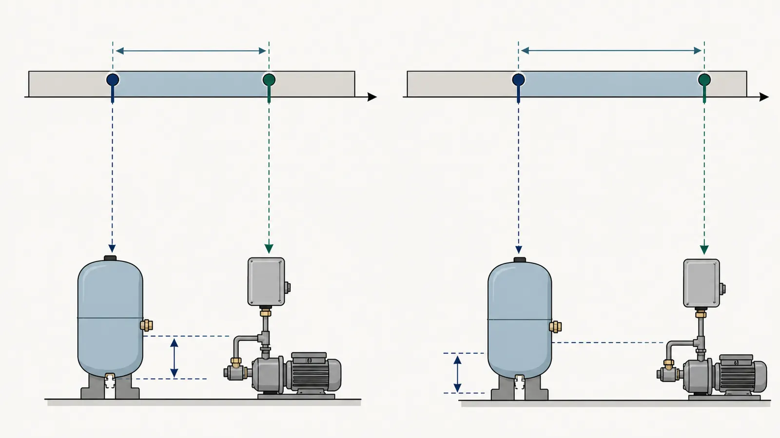
The pressure band affects two separate experiences:
- Pressure at the fixture. A 40/60 system may maintain a higher pressure range than a 30/50 system. The actual shower or faucet result still depends on elevation, pipe size, filters, treatment equipment, valves, flow demand, and the pump’s delivered pressure. A new switch cannot repair a clogged filter, a restricted pipe, a leaking service line, or a pump that is losing capacity.
- Water delivered from the tank during a cycle. The tank’s air cushion is compressed further at the higher pressure. For the same tank model, the published water yield per pump cycle can be lower at 40/60 than at 30/50. Pentair’s Pro-Source chart, for example, lists separate drawdown values for 20/40, 30/50, and 40/60; its listed values decline as the pressure band rises. (Pentair’s Pro-Source tank chart)
That second effect matters because a smaller drawdown can make the pump start more often for the same household use. Massachusetts’ Private Well Guidelines likewise say tank type depends on pump size, water use, and well yield, direct readers to manufacturer charts and procedures, and explain that a given captive-air tank stores less water as system pressure increases. The guideline gives the bounded example that a 10-GPM pump needs a larger tank at 40–60 psi than at 30–50 psi. (Massachusetts’ Private Well Guidelines)
A pressure upgrade is not a fault diagnosis
If the reason for the proposed change is “the pressure is low,” first separate a comfort preference from a system problem. A healthy system that is intentionally set to 30/50 is one decision. A system that cannot reach 50 psi, cycles rapidly, loses pressure overnight, has a gauge that does not match the switch, or has a tank with visible corrosion is a repair decision.
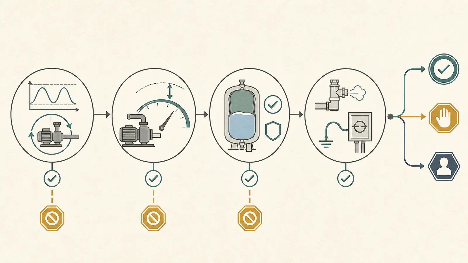
Do not use 40/60 to hide these symptoms. A higher cut-out can make an already marginal pump run longer without stopping. A higher precharge can put additional stress on a tank whose internal condition is unknown. The first safe outcome may be “repair or investigate,” not “buy a 40/60 switch.”
2. Gate 1: verify the pump can support 60 psi
The central pump question is not “What horsepower is printed on the motor?” It is “Can this installed pump build and maintain the proposed pressure at the real installation conditions, and can it stop reliably?” Pump output changes with lift, piping, water level, plumbing restrictions, and flow. A horsepower label alone does not provide the pump curve or prove the pressure available at the house.
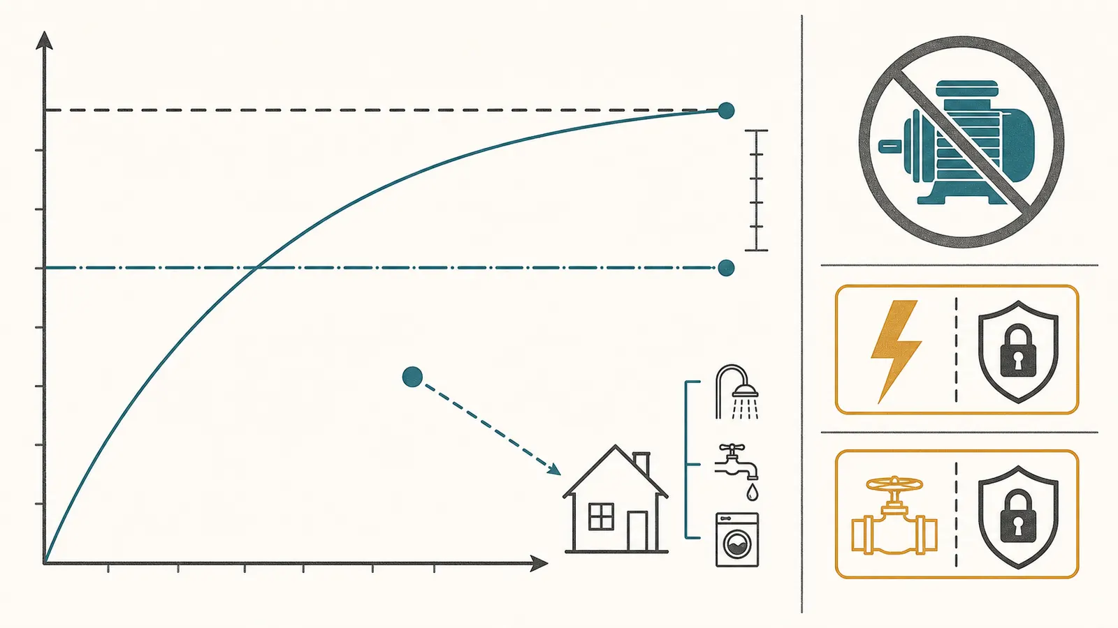
Pentair’s adjustment instructions define dead-head pressure as the pressure a pump produces when it is not moving water, and say the switch cut-off should always be at least 5 psi below that dead-head pressure. For a proposed 60-psi cut-out, that instruction implies a dead-head pressure of at least 65 psi for the covered pressure-switch arrangement. The same instructions say not to adjust the switch above 60 psi. This is a professional system check, not an invitation to close a valve or run a pump against a closed discharge. (Pentair’s pressure-switch adjustment instructions)
The 65-psi figure is a minimum relationship from that Pentair instruction, not a guarantee of good household pressure. A pump may technically reach a cut-out while delivering too little flow for a shower, irrigation zone, or simultaneous fixtures. A qualified person should use the exact pump model, pump curve, well conditions, and system demand to determine whether 40/60 is appropriate.
What you can record without testing live wiring
From a safe location, record what the gauge does during ordinary use. Do not remove the cover of the switch or control box to read a label. If the gauge is mounted where it can be read without touching electrical or pressurized components, note:
| Observation | What it may indicate | What it does not prove |
|---|---|---|
| Pump stops around 50 psi and restarts around 30 psi | The system may be operating near a 30/50 band | Gauge accuracy, pump capacity, or tank health |
| Pump runs but pressure stalls below its usual cut-out | A pump, well, restriction, leak, switch, gauge, or control problem needs diagnosis | That 40/60 will solve the problem |
| Pump reaches cut-out but takes unusually long | Reduced pump output, water-level change, restriction, or altered system condition is possible | That a higher cut-out is safe |
| Pump starts and stops repeatedly during a small demand | Loss of tank air, a waterlogged or damaged tank, leak, switch issue, or low drawdown is possible | That a larger switch setting is the right repair |
| Gauge falls when no fixture is in use | A leak, check-valve issue, pressure loss, or other fault is possible | Where the leak is or whether the tank is bad |
| Gauge is stuck, fogged, bouncing, or inconsistent | The pressure reading is not reliable enough for a decision | The switch setting or pump output |
The safe next step for a stalled, rapid-cycling, or unexplained system is a diagnosis by a qualified professional. Do not “test” the cut-out by closing a discharge valve. Pentair’s adjustment instructions specifically describe dead-head pressure as a hazardous operating condition and caution against running the pump against a closed outlet longer than needed for a qualified reading. (Pentair’s pressure-switch adjustment instructions)
The evidence a professional needs
Ask the professional to document the exact pump and motor model, pump type, well depth and water-level information if available, pump curve or manufacturer data, current pressure readings, flow at the relevant pressure, and whether the pump reaches cut-out within a reasonable time. “It is a 1-HP pump” is not enough. A useful quote should say whether the professional is changing only the switch, changing the tank precharge, replacing the tank, repairing the pump, correcting a restriction, or changing multiple components.
If the pump cannot support 60 psi with the required margin, keep 30/50 or repair the underlying system. Do not raise the cut-out simply because the home feels under-pressurized.
3. Gate 2: check the tank before changing precharge
The tank is the most important reason not to treat this as a switch-only job. A 40/60 arrangement changes the target precharge and the pressure range in which the tank operates. It does not make the tank newer, stronger, or internally inspectable.
The 2-psi rule is a starting point, not permission to adjust
Amtrol’s support page states that a precharged well-tank precharge should be 2 psi below the pressure-switch cut-in and lists 38 psi for a 40/60 setting. Pentair’s Pro-Source manual similarly lists 28 psi for 30/50 and 38 psi for 40/60, with the tank empty of water when precharge is set. (Amtrol’s well-tank support table, Pentair’s Pro-Source tank manual)
For a conventional, healthy tank under those instructions, the comparison is:
| Pressure-switch band | Example precharge target | Change from 30/50 |
|---|---|---|
| 30/50 | 28 psi | Baseline |
| 40/60 | 38 psi | 10 psi higher |
Do not apply the 38-psi number blindly. The installed tank’s manual, tank type, pressure rating, controller, and service condition control. Pentair’s same manual gives a different instruction for Pentek Intellidrive variable-frequency systems: 70% of system operating pressure, or 70% of the lower set point when two set points are used, with reference to the controller manual. That is why a constant-pressure or variable-speed system must leave this conventional branch. (Pentair’s variable-frequency precharge instruction)
Red flags that stop a precharge increase
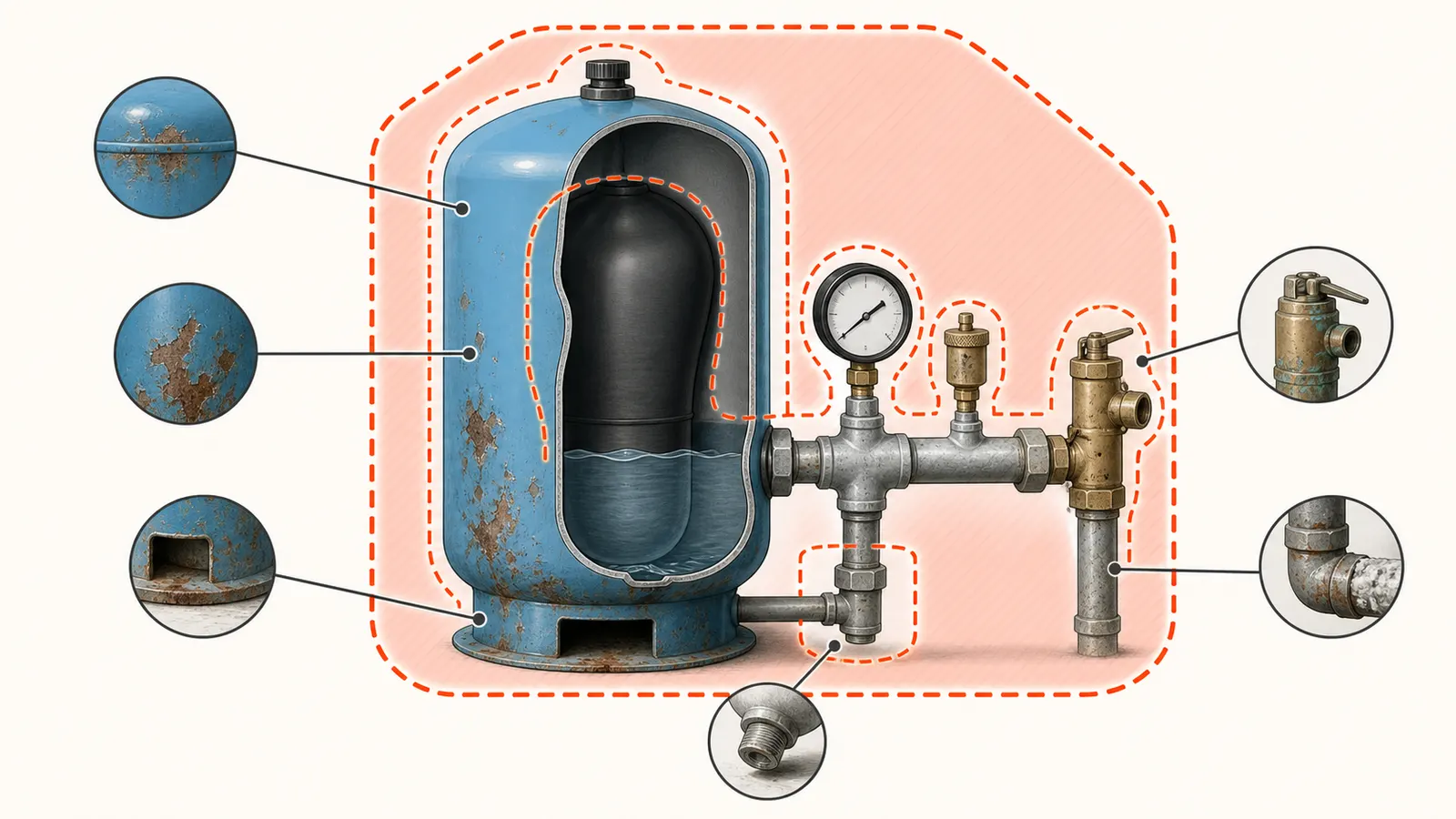
Amtrol’s well-tank manual is unusually direct about a higher precharge on a tank already in service. It says not to adjust or add pressure when there has been a loss of air, visible exterior corrosion, or a reduction in pump cycle time or precharge compared with the initial setting. The manual explains that reduced cycle time can result from lost tank air and may indicate internal corrosion; re-pressurization could then cause rupture or explosion. It also says only qualified professionals should check, adjust, or recharge tank precharge. (Amtrol’s precharged well-tank safety instructions)
Treat these as stop conditions:
- The tank has visible rust, pitting, a bulge, a split seam, a leak, or a wet area that cannot be safely identified.
- The tank has lost air repeatedly or the air-valve cap or valve leaks.
- The pump cycle has become shorter than it used to be.
- Water comes from the tank air valve, suggesting a failed bladder or diaphragm in a design where water should not be present there.
- The nameplate is unreadable, missing, or shows a maximum pressure below the proposed system pressure.
- The tank is an older non-bladder design and nobody has identified its air-volume-control requirements.
- The tank is installed where a failure could flood the home and there is no known drain or containment plan.
Do not pressurize a questionable tank to “see if it holds.” Do not remove the air-valve core, disconnect the tank, or drain a pressurized system as a homeowner experiment. The tank manual’s warning is about stored energy: a tank can look ordinary from the outside while its internal integrity is unknown.
Read the nameplate without disturbing the system
A homeowner-safe record can include a photograph or transcription of a readable label taken from a dry, stable position without opening a control enclosure or touching fittings. Capture the manufacturer, exact model, serial or date code if visible, nominal capacity, maximum working pressure, factory precharge if listed, connection size, and installation orientation. Also record whether the tank is a diaphragm, bladder, composite, galvanized, or another design only when the label or manual says so; do not infer the construction from color or shape.
The nominal gallon number is not the same as water delivered between pump cycles. Pentair’s published chart gives model-specific drawdown by pressure-switch setting, and the same physical model can deliver less drawdown at 40/60 than at 30/50. Use the exact model chart rather than a retailer’s generic table or a universal percentage. (Pentair’s Pro-Source drawdown chart)
4. Gate 3: confirm pressure protection and system compatibility
Changing a switch changes the pressure at which the pump is asked to stop. The tank, relief valve, plumbing, treatment equipment, water heater connections, filters, and other components must be compatible with the proposed maximum pressure. The switch itself is only one component in a pressure system.
Tank rating and relief valve
Amtrol’s manual for its 125-PSIG-rated tanks says the maximum system pressure must not exceed 125 psi or the applicable local requirement, whichever is less. It also requires a relief valve with a maximum relief pressure of 100 psi that is capable of discharging the pump’s rated capacity at maximum system pressure. Pentair’s Pro-Source manual likewise warns that if system discharge pressure can exceed the listed pressure limit, a relief valve capable of passing the full pump volume at that pressure is required. These are manufacturer instructions for the named products, not a national code for every tank. (Amtrol’s tank safety and relief-valve instructions, Pentair’s Pro-Source safety instructions)
From a safe observation position, record whether a relief valve is visibly present near the tank tee or pressure vessel, whether its discharge path is identifiable, and whether the nameplate or manual gives the tank rating. Do not lift the relief-valve lever to “test” it, remove it, cap it, install a smaller valve, or assume that a valve seen somewhere in the plumbing protects the tank. The professional must confirm placement, sizing, discharge, and isolation arrangements against the exact equipment instructions and local requirements.
Switch and motor compatibility
Pentair’s pressure-switch product information shows that a 40/60 switch can be sold for a broad range of pump horsepower, but a product range is not a selection rule for your installation. The professional must confirm the switch’s voltage, current rating, phase, enclosure, connection, low-pressure cut-off behavior, and compatibility with the motor, control box, disconnect, wire, and protective devices. If the proposed switch is a different style or has a low-pressure cut-off, its behavior and reset procedure also need to be understood. (Pentair Myers’ switch specifications)
Keep the electrical boundary firm. Do not open a switch cover, move an adjustment nut, pull wires, substitute a breaker, or verify voltage. A qualified electrical or well-pump professional should isolate the circuit, verify absence of voltage with appropriate equipment, and make the change according to the installed pump and switch instructions. The homeowner’s job is to record labels, symptoms, safe gauge observations, and the desired outcome.
Constant-pressure and variable-speed systems are a different branch
Some systems do not use a simple fixed 30/50 or 40/60 cycle. A variable-frequency drive changes pump speed in response to a pressure transducer or controller set point. A constant-pressure display may show a target pressure even though there is no conventional pressure-switch cut-in and cut-out pair to change.
If you see a controller, transducer, electronic drive, branded constant-pressure system, or an unfamiliar pressure-control panel, stop the 30/50-to-40/60 worksheet. Record the controller and tank model and use its current manual. Pentair’s Pro-Source instructions explicitly give a separate Intellidrive precharge method rather than the conventional 2-psi rule. (Pentair’s Intellidrive-specific tank instruction)
Do not change a controller set point because a mechanical 40/60 switch is available at a store. A constant-pressure system may have controller, motor, transducer, tank, cooling, and programming requirements that are invisible at the gauge.
5. Gate 4: record the current cycle and separate comfort from failure
Before choosing an action, make a record while the system is still at its known setting. This record is useful even if you ultimately hire someone. It helps the professional tell a pressure-preference request from a pump, tank, gauge, switch, leak, or well-yield problem.
Safe observation procedure
Use only ordinary observation from a safe location. Do not service the tank, switch, wiring, well, pump, relief valve, or pressurized fittings.
- Let the system sit at its normal setting. Turn off avoidable household demand such as irrigation, a washing machine, a dishwasher, treatment regeneration, and multiple fixtures. Do not close or adjust an unidentified valve.
- Locate the pressure gauge only if it can be read without touching electrical equipment or pressurized connections. Record the resting pressure and whether the gauge is readable, fogged, stuck, or bouncing.
- At one ordinary downstream cold-water fixture, use a small, safe demand that will not flood the area or contact electrical equipment. Observe whether pressure falls smoothly, the pump starts, and the pump stops. Stop if the pump runs continuously, the pressure behaves unexpectedly, or the discharge is unsafe.
- Record the approximate start and stop readings shown on the gauge. Do not call them exact if the gauge is coarse or hard to read.
- If a professional has already measured flow or cycle time, record the method and conditions. Do not substitute a guessed flow rate from the pump horsepower or tank size.
- Repeat only if the observation is safe and consistent. A single odd cycle is a reason to investigate, not a reason to change the switch.
The result is an observation record, not a pressure-vessel inspection. It cannot prove that the tank air charge is correct, the bladder is intact, the pump curve is adequate, the gauge is accurate, or the well has sufficient yield.
The homeowner record
| Record this | Current system | Proposed change or professional answer |
|---|---|---|
| Pressure at pump start | Note the gauge reading and confidence | 40 psi target confirmed or not confirmed |
| Pressure at pump stop | Note the gauge reading and confidence | 60 psi target confirmed or not confirmed |
| Pump behavior | Normal stop / long run / continuous / rapid cycling | Can the pump reach the proposed cut-out with margin? |
| Gauge condition | Clear / fogged / stuck / bouncing / unknown | Gauge verified or replaced by professional? |
| Pump and motor model | Record from safe label or paperwork | Exact pump curve or manufacturer data reviewed? |
| Controller type | Mechanical switch / electronic / unknown | Conventional branch or controller-specific branch? |
| Tank manufacturer and model | Record the full label | Exact manual and chart located? |
| Tank maximum pressure | Record the nameplate value | Meets the proposed system pressure? |
| Tank condition | No visible concern / corrosion / leak / air loss / unknown | Repair or replacement required? |
| Relief valve | Present and identifiable / unknown | Placement, rating, capacity, and discharge confirmed? |
| Filters and treatment | Clean, restricted, or unknown | Could the restriction explain low pressure? |
| Water quality concern | None known / recent change / contamination concern | Stop water use and contact local authority if needed |
| Preferred outcome | More pressure / fewer symptoms / diagnosis / quote | Keep 30/50, repair, or evaluate 40/60 |
A bounded drawdown calculation
If the professional has documented pump flow and a minimum run-time requirement, the first drawdown target can be represented as:
minimum drawdown = pump flow in gallons per minute × minimum run time in minutes
For example, a documented 8-GPM pump and a documented 1-minute minimum run time produce 8 gallons of minimum drawdown. That is not a recommendation for every pump; it is a transparent calculation using the supplied inputs. The candidate tank must then be checked against the exact manufacturer chart at the actual pressure band. If a demand study gives additional supplemental storage, add that supplemental amount. If it already gives a total peak-demand storage requirement, compare it as a total rather than adding it again.
This matters more at 40/60 because the same tank may publish less drawdown at the higher pressure band. Massachusetts’ guidance says manufacturer charts and procedures should be used and gives the bounded example that a 40–60 system needs a larger tank than a 30–50 system for the same 10-GPM pump. Pentair’s model chart demonstrates the same relationship for its Pro-Source tanks. (Massachusetts’ Private Well Guidelines, Pentair’s Pro-Source tank chart)
Do not use “a 44-gallon tank,” “a 1-HP pump,” or “40/60 is standard” as the calculation. Those labels omit the exact drawdown chart, operating pressure, pump output, tank condition, and local installation details.
6. Decide: keep 30/50, repair first, or obtain a 40/60 quote
Use the following decision matrix after recording the facts. “Pass” means evidence is present; “unknown” is not a pass.
| What the record shows | Decision | Why |
|---|---|---|
| Conventional fixed-speed system; pump documentation or qualified test supports the proposed cut-out; tank model and rating are known; no corrosion or lost-air warning; relief protection is confirmed | Obtain a 40/60 compatibility quote | A professional can apply the exact switch and tank manual, verify the pump and electrical arrangement, set the system, and confirm operation |
| Pressure is acceptable at 30/50 and the only goal is a modest comfort change, but the pump curve or tank condition is unknown | Keep 30/50 for now | The missing facts are compatibility gates, not paperwork details |
| Pump stalls, runs continuously, takes much longer to stop, or cannot reach the current cut-out | Repair or diagnose first | Raising cut-out can extend the fault and may prevent normal shutoff |
| Tank has visible corrosion, lost air, shortened cycling, a leak, or an unknown rating | Do not increase precharge; obtain a tank/system assessment | Amtrol warns that re-pressurizing a damaged or compromised in-service tank can cause rupture or explosion |
| Relief valve is missing, inaccessible, unknown, incorrectly rated, or apparently isolated | Stop and hire | Protection must be confirmed before a pressure change |
| System has a variable-speed drive, transducer, electronic controller, or constant-pressure package | Use the controller-specific method | Conventional 30/50 and 40/60 logic may not apply |
| Gauge is unreadable or the switch behavior does not match the gauge | Repair or verify the measurement | You cannot make a pressure decision from an untrusted reading |
| Water quality changed after a repair, flooding, drought, or plumbing modification | Address water safety separately | A pressure decision does not establish that private-well water is safe |
Amtrol’s manufacturer warning is the decisive boundary for the compromised-tank row. Its manual says a licensed professional must install and periodically inspect and service the tank, and warns that corrosion, air loss, or reduced cycle time can make additional pressure dangerous. (Amtrol’s precharged well-tank manual)
When low pressure is the real problem
If the home has low pressure at only one fixture, inspect that fixture’s aerator or local shutoff only if the work is ordinary, unpressurized, and safe. If pressure is low throughout the home, record filter condition, treatment equipment, visible leaks, gauge behavior, pump run behavior, and pressure at more than one safe point. Do not conclude that the switch is at fault just because replacing it is easy to describe.
If the pump reaches its normal cut-out but pressure drops sharply when water flows, the issue could be pump capacity at flow, a restriction, a leak, well yield, a failing check valve, or a measurement problem. If the pump never reaches the current cut-out, a 40/60 switch is not a pressure upgrade; it is a request for an even higher stopping point that the system may not achieve.
When water safety enters the decision
Pressure work does not sanitize a private well or prove the water is potable. If there has been flooding, a suspected chemical or sewage event, or an unexplained change in appearance, odor, taste, or health-related test result, use a known-safe water source and contact the local health or environmental authority for testing and return-to-use instructions. Massachusetts says local boards of health regulate private-well criteria in that state, and its guidelines are not a substitute for local statutes or regulations. (Massachusetts’ Private Well Guidelines overview)
If a pump or plumbing modification is completed, MassDEP recommends a bacterial test after disinfection and substantial flushing of the system and identifies recent well repair or pump/plumbing modification as a reason for more frequent testing. This is Massachusetts guidance; the local authority and the exact work performed determine what applies elsewhere. (MassDEP’s private-well FAQ)
7. Bring a quote-ready record to the professional
The best request is specific enough that the professional can price the real work and explain why. Bring or send:
- The current cut-in and cut-out observations, with confidence notes about the gauge.
- The requested outcome: higher fixture pressure, a planned switch replacement, rapid cycling, low pressure, or a suspected fault.
- The pump, motor, control-box, pressure-switch, gauge, tank, and controller model information visible without opening equipment.
- The tank maximum pressure, nominal capacity, exact model, age or date code if available, and any visible corrosion, leak, or water at an air valve.
- A description of pump run time, failure to reach cut-out, rapid cycling, pressure loss when no water is used, and what demand was active during the observation.
- The relief-valve location and any readable rating, without operating or removing it.
- The available space and access constraints if a tank replacement may be needed.
- Any recent well, pump, plumbing, flooding, drought, or water-treatment event.
- The applicable local board-of-health, plumbing, electrical, or well requirements if known.
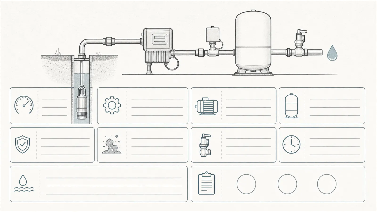
Ask the professional to answer these questions in the quote or service note:
- Can the installed pump reach and hold the proposed 60-psi cut-out under the actual system conditions, with the required margin below dead-head pressure?
- What exact pump and tank documentation supports the proposed switch and precharge?
- Does the current tank’s condition make a higher precharge unsafe or uneconomical?
- What drawdown does the exact tank model publish at 40/60, and does it satisfy the pump’s minimum-run and demand requirements?
- Is the relief valve correctly sized, placed, discharged, and protected from isolation for this system?
- Does the switch match the pump motor, controller, voltage, current, wiring, and any low-pressure cut-off requirement?
- Is the system conventional fixed-speed, or does it require a variable-speed/controller-specific method?
- What will be tested after the work: cut-in, cut-out, pump run time, leaks, relief protection, gauge behavior, and water quality if plumbing was modified?
The quote should distinguish a switch-only change from a tank replacement, pump repair, gauge replacement, relief-valve correction, filter or treatment repair, electrical work, or well investigation. If the recommendation is simply “install 40/60 and set the tank to 38,” it is incomplete until the professional has addressed pump capacity, exact tank instructions, tank condition, and relief protection.
Bottom line
You can change from 30/50 to 40/60 only when the installed system passes the compatibility gates. The numbers are straightforward—40 psi cut-in, 60 psi cut-out, and often 38 psi tank precharge for the specific conventional manufacturer instructions cited here—but the decision is not just about numbers. Verify the pump, tank, protection, control type, and local requirements. Keep 30/50 when the system is healthy but the evidence is incomplete. Repair first when pressure behavior is abnormal. Stop and hire when the tank is questionable or electrical, well, pressurized, or confined-space work would be required.
Sources and scope
Evidence behind this page
- Amtrol — Well Tank Support
Amtrol's Well-X-Trol support guidance and table; use the exact installed tank manual when another tank design or product instruction differs.
- Amtrol — Pre-pressurized Water System Well Tanks Installation, Operation & Maintenance Instructions
Amtrol's precharged well-tank manual, including its 125-PSIG-rated tank warnings; this is a manufacturer safety instruction, not a diagnosis of every tank brand.
- Amtrol — Pre-pressurized Water System Well Tanks Installation, Operation & Maintenance Instructions
Amtrol's specific 125-PSIG-rated precharged well-tank installation requirements; local rules and the installed tank's nameplate remain controlling.
- Pentair — Pro-Source Steel Pressure Tanks Manual
Pentair Pro-Source/Pro-Source Plus steel pressure-tank models and their published chart; do not transfer its drawdown gallons to another model or tank design.
- Pentair — Pro-Source Steel Pressure Tanks Manual
Pentair's safety instructions for Pro-Source steel pressure tanks; the article uses them to set a homeowner stop boundary, not as a universal electrical or plumbing code.
- Pentair Myers — Well System Pressure Switches
Pentair's Myers pressure-switch product family; availability of a 40/60 switch does not prove that a particular installed pump, tank, motor, wiring system, or local installation supports it.
- Pentair — Adjusting Well Pump Pressure Switches Instructions
Pentair's adjustment instructions for the covered pressure-switch arrangements; a qualified professional must apply the exact pump and switch instructions to the installed system.
- Commonwealth of Massachusetts — Private Well Guidelines
Massachusetts guidance for private wells; it is not a national plumbing or electrical code and does not select a tank or authorize a pressure-switch change in another jurisdiction.
- Massachusetts Department of Environmental Protection — Private Well Guidelines
Massachusetts-specific regulatory context; other states and localities may assign authority differently, so the homeowner must check the local authority for the property.
- Pentair — Pro-Source Steel Pressure Tanks Manual
Pentair's Intellidrive-specific instruction; it demonstrates that variable-frequency systems require a controller-specific method and is not a universal setting for every constant-pressure product.
- Massachusetts Department of Environmental Protection — FAQs: Private Wells
Massachusetts private-well water-quality guidance; it is a recommendation and does not replace local board-of-health requirements or the exact disinfection and sampling instructions for the property.