Can I Move My Well Pressure Tank Into My House?
Use your tank label, pump layout, pressure controls, pipe route, elevation, freeze exposure, drainage, and local-code review to decide safely.
The short answer
Usually, a well pressure tank can be relocated into a house only as part of a system redesign. Confirm the tank model and rating, keep the tank downstream of the pump, preserve or relocate the pressure controls appropriately, protect every exposed component from freezing, provide leak drainage and service access, and have plumbing and electrical work reviewed locally. A tank move will not fix an exposed or freezing well line.Observation flow
What is the system doing?
Choose the closest visible pattern. Stop immediately for sparking, hot wiring, uncontrolled pressure, or a damaged tank.
Can I Move My Well Pressure Tank Into My House?
Yes—often, but not as a simple “disconnect it here and reconnect it there” project. A pressure tank is one part of a pump-and-control system. A safe relocation needs to preserve the tank’s approved use and pressure rating, keep it downstream of the pump, account for the pressure switch or electronic control, maintain an appropriate pipe route, protect every exposed component from freezing, control leak and flood damage, and leave enough access for service.
Separate water quality from the relocation decision. This page and worksheet are not a water-quality test, contamination investigation, or certification that the water is safe to drink. If contamination or unsafe water is suspected, do not open the well or alter the well/plumbing to investigate. Pause the relocation and contact the local health or environmental department and a qualified well professional for testing and any disinfection plan; use a state-certified drinking-water laboratory and follow the applicable retesting guidance. CDC directs private-well owners to use certified laboratories and contact their health department about testing and what to do next. CDC also advises contacting a health department or well-water contractor about treatment and testing again to confirm that treatment worked.
The most important distinction is this: moving the tank indoors may protect the tank, but it does not automatically protect the water line between the well or pump house and the home. Manufacturer instructions consistently treat the tank, piping, controls, relief protection, and installation location as one system. Global Water Solutions says its well tank should be downstream from the pump, installed in a covered dry position, protected from freezing, and installed in accordance with local and state plumbing codes. Pentair’s WellMate instructions likewise say never to install the tank where it can freeze.
Use the worksheet below to decide which of three outcomes fits your system:
- Potentially feasible: the tank label and condition are known; the new room is dry, supported, serviceable, and freeze-protected; the pump/control arrangement can be preserved; and a professional can verify the route and local requirements.
- Review before moving: the tank is remote from the pump, the pressure switch is separate, the route changes elevation or pipe size, the system uses electronic or variable-speed controls, or the tank’s condition or model is uncertain.
- Stop: the tank is corroded, leaking, damaged, unlabelled, or still pressurized; the proposed location can freeze or flood; the line or well components remain exposed; or the job would require opening energized controls, opening the well, pulling a pump, entering a confined space, or manipulating pressurized equipment.
1. Start with the tank and system identity
Before deciding where the tank should go, identify what you have. A “well pressure tank” can mean a precharged diaphragm or bladder tank, an older plain-steel tank, a tank paired with a jet pump, a tank paired with a submersible pump, or part of an electronic or variable-speed control system. The relocation logic changes with the arrangement.
Record what is visible without opening anything
With the system operating normally and covers closed, photograph or transcribe:
| Record | Where to look | What it tells you | What not to infer |
|---|---|---|---|
| Manufacturer, model, serial, tank type | External tank label | Which manual and rating apply | Do not assume two tanks of similar size use the same precharge or mounting method |
| Maximum working pressure and temperature, if shown | External data label | The boundary for the proposed system | Do not use a pressure-switch number as the tank rating |
| Connection size and orientation | Tank tee, bottom connection, or label | Whether the new plumbing can match the existing arrangement | Do not reduce the pump-to-tank pipe just because a nearby fitting is smaller |
| Pump type | Visible jet-pump body, control box, or records | Whether the pump is at the building or down the well and what controls may be involved | Do not open a well seal or pull a pump to identify it |
| Pressure switch, transducer, or controller | External location and label only | Whether the control is at the tank, at the pump, or in a separate enclosure | Do not remove a control cover or touch wiring to read a setting |
| Gauge behavior | Gauge with the system at rest and during normal use | Approximate cut-in/cut-out behavior for the professional to verify | A gauge observation is not proof that the switch is calibrated |
| Corrosion, bulging, dampness, or a leak | Exterior and floor around the tank | Whether the existing tank should be evaluated rather than moved | Never add air to a corroded or damaged tank |
The manufacturer warning is not a formality. Amtrol warns not to adjust or add pressure when there has been air loss, visible exterior corrosion, or reduced cycle time or precharge, because internal corrosion and repressurization can create a rupture or explosion hazard. For a tank that is leaking, corroded, damaged, or missing its identity label, the safe decision is review or replacement assessment, not relocation.
Do not open an energized pressure-switch or pump-control enclosure. Do not test live wiring. Do not open the well, disconnect a pressurized fitting, remove the tank, or attempt to “bleed off” pressure by loosening a union. If a professional needs the switch settings or precharge verified, give them the photographs, gauge observations, model information, and access to the site.
Decide whether this is a tank move or a control-system change
For a conventional pressure-switch-controlled well system, the tank and pressure switch are commonly related at the tank tee. If the pressure tank is moved while the switch stays far away, the pressure seen at the switch can differ from the pressure at the tank because of pipe friction and elevation. Both GWS and Amtrol direct installers to keep the tank close to the pressure switch or place the switch near a remotely located tank, specifically to reduce friction, switch bouncing, and elevation effects. Amtrol’s manual makes the same location point for its well tanks.
If your system uses a transducer, variable-frequency drive, electronic controller, constant-pressure package, air injector, multiple tanks, or a separate pump control box, treat the move as a system redesign. The existing settings and connection logic may not transfer to a different location. GWS gives different precharge guidance for conventional pressure switches, larger switch differentials, electronic controls, and variable-speed controls; that is a practical reason not to copy a generic “two psi below cut-in” rule from the internet. Read the GWS model-specific precharge section here.
2. Run the relocation screen
Use this table from left to right. A single stop condition is enough to pause the move.
| Check | Observe | Interpret | Safest next step |
|---|---|---|---|
| Tank identity | Model, rating, use, condition | Known and compatible is a prerequisite | Gather the exact manual; unknown or damaged means professional review |
| Pump relationship | Tank is on the pump discharge, not on an unintended suction or isolated branch | The tank must remain downstream of the pump for the described GWS arrangement | Have the installer trace flow direction and valves |
| Control relationship | Switch/transducer/control is at or near the tank, or the manufacturer allows the proposed arrangement | A remote control may see a different pressure and cycle poorly | Plan the tank and control together unless the control manufacturer says otherwise |
| New room | Dry, covered, firm, level, non-damaging, accessible | The room can be suitable if it will not flood or freeze | Choose a leak-safe base and clear service approach |
| Pipe route | Same or approved size, known material, measurable length, no unplanned restriction | Added length, fittings, or a smaller pipe can add friction | Have the route calculated or checked against the pump curve |
| Elevation | Vertical difference from pump/well-side connection to tank and from tank to key demand | Elevation changes pressure head; the pump may have to overcome more head | Record vertical feet; do not rely on horizontal distance alone |
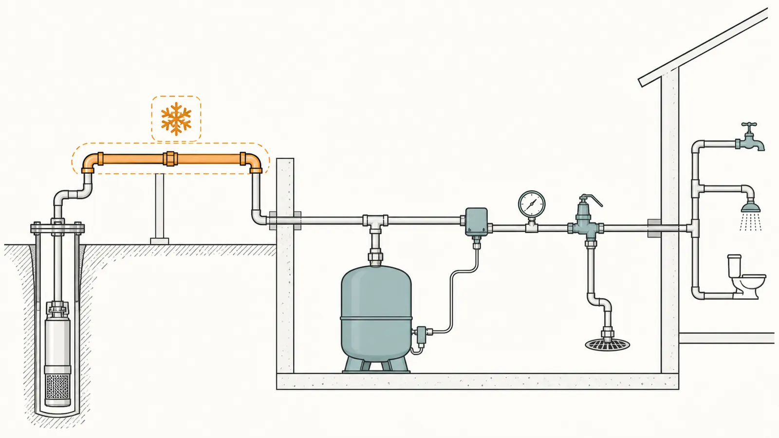
| Remaining freeze points | Exposed service line, pitless adapter area, pump house, tank tee, drain, relief discharge, or wiring | An indoor tank does not protect an exposed line or component | Protect, reroute, drain, or redesign the exposed section |
| Water quality | Suspected contamination, unsafe water, or an unverified potable-water concern | A relocation record cannot determine whether water is safe to drink or identify the contaminant | Do not open or alter the well/plumbing to investigate; contact the local health authority and a qualified well professional for certified-lab testing and disinfection guidance |
| Water and service | Drain, drip pan where appropriate, shutoffs/unions, relief discharge, access | A leak can become a basement flood; a hidden tank is hard to maintain | Obtain a plumbing layout and local review |
| Electrical | Pump power, disconnect, grounding/bonding, control enclosure, wet-location concerns | A plumbing move can disturb electrical protection | Use a qualified electrician or well professional for wiring work |
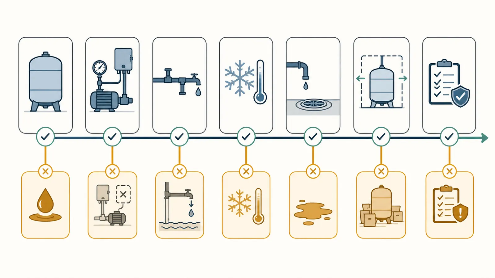
The result is not a permit decision. It is a homeowner triage tool. Local rules differ. For example, Ohio’s private-water-system rule addresses pressure-tank locations and relief valves with state-specific exceptions and conditions; that is evidence that “allowed in a basement” cannot be treated as a nationwide answer. Ask the local plumbing authority, well contractor, or licensed plumber what review, permit, inspection, or well-standard requirements apply at your address.
3. Map the hydraulic route before moving anything
The proposed room matters less than the route from the pump to the tank and from the tank to the home. Draw a simple plan with four points:
- The well pump or jet-pump discharge.
- The proposed tank tee and pressure control.
- The house distribution connection.
- The highest or most pressure-sensitive demand you care about, such as an upstairs shower or treatment equipment.
Measure and record:
- the pipe’s outside diameter and, if known, nominal size;
- pipe material;
- approximate length of each straight section;
- the number and type of major fittings, filters, softeners, check valves, and shutoffs;
- vertical rise or drop between the pump-side connection and the proposed tank location;
- exposed sections and the temperatures or conditions they experience;
- where the relief valve, drain, gauge, unions, and shutoffs would land;
- whether the route introduces a smaller pipe than the existing pump-to-tank line.
Do not guess from a short visible fitting. A professional may need the actual pipe size, material, pump capacity, and operating pressure to check the route.
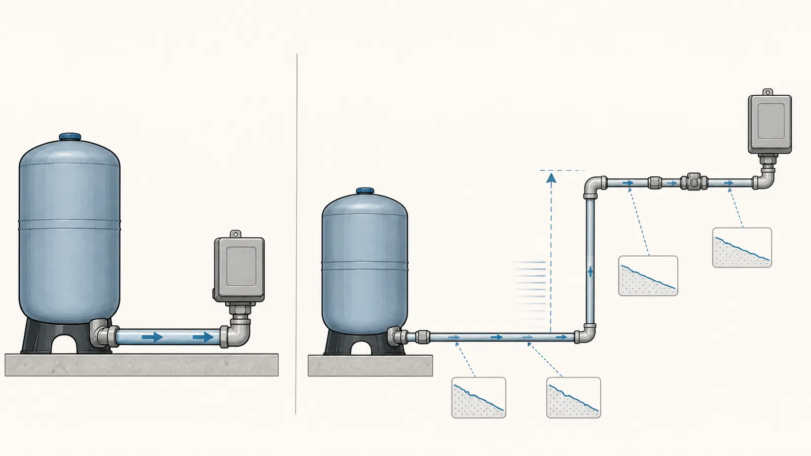
A useful elevation check
For a first-pass screen, record vertical elevation in feet. Water pressure changes by about 0.433 psi per foot of elevation; the Alaska Department of Environmental Conservation waterworks math manual gives the equivalent relationship as 1 psi = 2.31 feet of head. See the state conversion reference.
Screening calculation:
elevation pressure effect ≈ vertical feet × 0.433 psi/foot
Example: if the proposed tank is 12 vertical feet higher than the current pump-side connection, the static elevation effect is approximately 12 × 0.433 = 5.2 psi. That is not a complete pump calculation. Flow friction, fittings, filters, pump performance, pressure-switch settings, and the actual pumping water level also matter.
The Michigan Water Well Manual describes total dynamic head as elevation head plus friction head loss plus pressure head and directs the designer to consider pipe diameter, length, material, fittings, pump flow, and pressure-switch cut-out. That is the right mental model for a relocation: a longer or higher route may be workable, but it should be checked against the pump’s performance rather than approved by eye.
What a tank move can change
A move can change:
- pressure at the switch or transducer;
- friction loss between pump and tank;
- pressure available at higher fixtures;
- pump run time and cycling behavior;
- the location of the relief valve and discharge path;
- how quickly a freezing section can damage the system;
- access to the tank for future service.
It does not change the well yield, pump horsepower, pump drop-pipe condition, or the depth and condition of the well. If the underlying problem is low well yield, a failing pump, a blocked service line, or a frozen line outside the house, relocating the tank may add work without solving the symptom.
4. Check freeze protection as a complete path
Moving the tank into a heated basement is most helpful when the tank itself is the vulnerable component. It is not a complete freeze strategy unless the full water path and control arrangement are reviewed.
Trace the line from the tank room toward the well and mark every section that is:
- outside the heated envelope;
- in a pump house, garage, crawlspace, shallow trench, well pit, or unheated chase;
- near a door, foundation penetration, rim joist, or other draft path;
- connected to a valve, drain, filter, gauge, relief valve, or fitting that can retain water;
- exposed to floodwater, condensation, or standing water;
- adjacent to electrical equipment that must remain dry and accessible.
The manufacturer wording is deliberately broad. GWS says to protect the tank, piping, and system components from freezing. Pentair specifically says never to install its WellMate tank where it can freeze. Neither statement gives a universal safe outdoor temperature, insulation thickness, heat-cable recipe, or guarantee that a tank move fixes the line. Those details depend on climate, exposure, burial, heat loss, local practice, and the specific component instructions.
Freeze-point decision matrix
| Finding | What it means | Do not infer | Next action |
|---|---|---|---|
| Tank is the only exposed component and the new room is reliably protected | Relocation may address the principal freeze exposure | The house alone protects the incoming line | Have the installer verify the entire route and penetrations |
| Incoming line remains in a freezing pump house or shallow/exposed section | The failure point may remain after the move | A warm tank can thaw or protect a frozen line | Reroute or protect the line; do not simply move the tank |
| Gauge, relief valve, drain, or tank tee remains outside | Small components can still freeze or leak | A large tank is the only risk | Include every component in the freeze and service plan |
| System is seasonal or the building is left unheated | Freeze protection may require a documented shutdown or drain procedure | Closing one valve makes the system safe | Use the exact manufacturer/system procedure and a qualified professional where depressurization or electrical isolation is involved |
| Existing tank has corrosion or a damaged connection | Moving it can disturb a hazardous pressure vessel | New location makes an old tank safe | Stop; have the tank condition assessed |
Do not use an open flame or improvised heat source on a frozen pipe or tank. Do not energize a pump against an unknown frozen blockage. If the system has already frozen, shut down the pump using the normal disconnect only if that can be done safely without opening a cover or contacting live parts, then call a qualified professional.
5. Plan the new room for leaks, service, and controls
A basement is often attractive because it is warmer and closer to the home plumbing, but “indoors” is not the same as “suitable.” GWS says the tank should be in a covered, dry position, should not rub against surrounding hard surfaces, and should be placed to prevent water damage from leaks. Amtrol’s installation information calls out a drip pan connected to an adequate working drain.
Use these questions during a walk-through:
- Is the floor firm and level enough for the tank’s approved base or stand?
- Can the tank be supported without hanging its weight from piping that was not designed for it?
- Can a technician see the label, gauge, relief valve, unions, drain, and connection points?
- Can the tank be removed later without dismantling finished walls or moving unrelated equipment?
- Where would a leak go? Is there a suitable pan or drain based on the tank manual and local practice?
- Could a relief discharge or failed fitting spray onto electrical equipment, stored belongings, or finished surfaces?
- Are shutoff valves and unions arranged so the system can be serviced after safe isolation and depressurization?
- Is the room protected from flooding, sump overflow, condensation, and freeze conditions?
- Does the proposed location conflict with required electrical clearances, access, or working space?
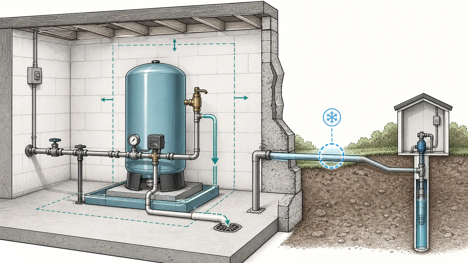
For a vertical tank, do not assume the old stand or floor condition is adequate. Pentair instructs installers to place its tank vertically on a level surface with the base fully supported. The exact support method is model-specific. Follow the tank’s instructions rather than improvising a wall bracket or strap.
Relief protection is another non-negotiable review item. Pentair requires an adequately sized relief valve on the tank inlet line, not isolated from the tank by a check valve, and says the valve must prevent the tank’s maximum operating pressure from being exceeded. Amtrol’s manual similarly specifies a relief valve and pump-capacity discharge requirements for its product line. These are manufacturer requirements for the named systems, not permission to select a generic valve by appearance. The professional needs the tank label, pump capacity, control settings, and local requirements.
6. Decide whether the tank and pressure controls move together
For many conventional systems, the most defensible relocation concept is to move or reconfigure the tank tee and its pressure-control point as a coordinated assembly, while leaving the pump and well-side infrastructure in place. That still requires qualified plumbing and electrical work. It is not a homeowner instruction to disconnect the assembly.
Conventional pressure switch
If the switch is mounted at the tank tee, ask the installer to evaluate moving the switch with the tee or placing it near the new tank. The goal is not a universal distance; the goal is to keep the pressure-sensing point representative of tank pressure and compatible with the manufacturer’s arrangement. GWS says a remote tank should have the pressure switch near the tank and that the tank should be as close as possible to the switch. Amtrol says the tank should be as close as possible to the pressure switch to limit friction, switch bouncing, and elevation differences.
Electronic, transducer, or variable-speed control
Do not assume the conventional switch logic applies. GWS distinguishes between a pressure-switch-controlled pump, a system with a larger pressure differential, and electronic or variable-speed controls when describing precharge. The system may rely on a transducer location, a controller’s wiring, a sensor cable, or a manufacturer-specific control sequence. Photograph the equipment labels with covers closed and ask for the exact installation manual.
Multiple tanks
If there is more than one pressure tank, record all models and how they are connected. GWS says multiple tanks should have equal precharge and be installed on a header so they receive balanced pressure, with the control centrally located. That instruction is specific to the GWS arrangement. Do not move one tank and leave the others in place without a system review.
Precharge: document, do not improvise
Precharge is not a universal number. The supplied manuals demonstrate why:
- GWS gives 2 psi below cut-in for a pressure-switch differential up to 30 psi, but a different approach for larger differentials, electronic controls, and variable-speed controls.
- Amtrol’s example for a 30/50 psi switch uses 2 psi below cut-in, but its safety warnings limit when a homeowner should adjust a tank in service.
- Pentair WellMate gives its own product-specific procedure and a 4 psig differential below the low-pressure limit in the supplied instructions.
The safe homeowner action is to record the visible model, the normal gauge behavior, any label information, and symptoms such as rapid cycling. Do not remove an air-valve cap, add air, release air, or check precharge on an installed tank unless the exact manual, tank condition, isolation, drainage, and depressurization have been verified by a qualified professional. Pentair warns that the tank and connected system must be completely discharged of air and fluid pressure before disassembly.
7. Know when the move will not solve the real problem
Relocation is a poor first move when the symptom points elsewhere. Use this diagnostic matrix to frame the professional conversation.
| Symptom or finding | Possible system area | Why relocation may miss it | Bring to the professional |
|---|---|---|---|
| Tank or line freezes | Exposed tank, service line, valve, or well-side piping | An indoor tank may leave the actual freeze point outside | Marked route, photos, building temperatures/conditions, and where ice or damage appeared |
| Pump cycles rapidly | Precharge, failed diaphragm/bladder, incorrect tank sizing, switch/control issue, leak, or waterlogged plain-steel tank | Moving a faulty tank does not restore correct drawdown or control | Cycle timing, gauge movement, tank model, recent changes, and visible corrosion |
| Low pressure at upper fixtures | Elevation, friction, filter/softener restriction, pump performance, or pressure settings | The new tank may add or remove head but does not prove the pump can deliver the demand | Fixture symptom, vertical rise, pipe size/material/length, filter status, and pressure observations |
| No water after cold weather | Frozen line, pump/control issue, power issue, or well problem | The tank location may be unrelated to the blockage | When it stopped, weather/exposure, normal disconnect status, and any safe external observations |
| Water in the basement | Tank, relief valve, drain, fitting, pan, or nearby plumbing | Moving the tank without drainage planning can move the flood risk indoors | Leak location, photos, whether the pump was safely isolated, and floor/drain conditions |
| Pressure gauge or switch behaves oddly | Gauge, switch, remote control location, friction, or elevation | A longer route can worsen control behavior | Gauge readings during normal use, control labels, pipe route, and whether the switch is remote |
The tank is an energy-storage component that reduces pump starts and supplies water while the pump is off. GWS describes the pressure tank’s role in reducing frequent starts and extending pump run time when properly sized. That function depends on the tank, control settings, pump, and system demand working together. A relocation should preserve the operating design or be treated as a redesign.
A practical “do not move yet” list
Pause and arrange a qualified site review if any of these are true:
- you cannot read the tank model or maximum working pressure;
- the tank is corroded, bulging, leaking, or has a damaged connection;
- the tank is a plain-steel or air-injection system and you do not know its maintenance arrangement;
- the pressure switch or controller is remote, electronic, or tied to a variable-speed pump;
- the new route is smaller, longer, higher, or more complex than the old route;
- an exposed line, valve, drain, or control remains in a freezing area;
- the basement can flood or has no safe leak-drainage plan;
- the plan requires opening a well, pulling a pump, opening a control box, or working on live wiring;
- the tank, fitting, or connected pipe is still pressurized;
- contamination or unsafe water is suspected, or potable-water safety has not been established by appropriate testing;
- local plumbing, electrical, well, or health requirements have not been checked.
8. Prepare the professional handoff and final decision
A useful site-review packet is more valuable than a guess at a universal tank distance. Bring:
- Exterior photos of the tank label, tank base, gauge, visible control enclosure, pump house, well-side route, and proposed room.
- The tank manufacturer, model, serial, connection size, maximum pressure, and stated use.
- Pump type, make/model/horsepower if known, and whether the pump is submersible, jet, booster, constant-pressure, or variable-speed.
- Visible gauge observations: normal low and high readings, how long the pump runs, and whether cycling is rapid. Do not remove the control cover to obtain a setting.
- A sketch with pipe material, nominal size if known, approximate length, fittings, filters, check valves, shutoffs, and vertical elevation change.
- Every remaining freeze point, including the line between the house and pump or well.
- The proposed room’s floor, drain, pan, flood, access, and electrical conditions.
- Your local jurisdiction and any well record, prior installation invoice, manual, inspection note, or repair history.
Ask the professional to answer these questions in writing or on the marked-up sketch:
- Is this tank approved for the water service and proposed location?
- Is the existing tank condition safe to move, or is replacement more sensible?
- Does the pump-to-tank route preserve pipe size and acceptable friction/elevation performance?
- Should the pressure switch, transducer, controller, gauge, relief valve, drain, and tank tee move together?
- What exact precharge and switch/control settings apply to this tank and control system after safe isolation?
- Which line or component remains the freeze point after the tank moves?
- How will a leak or relief discharge be contained and drained?
- What plumbing, electrical, well, permit, inspection, or health requirements apply locally?
- What service clearances and access should remain around the tank and controls?

Final decision
Choose move after review when the tank is identified and sound, the proposed room is dry and supported, the complete route is freeze-protected, the controls are compatible and appropriately located, the relief and drainage plan is clear, the pump can handle the hydraulic change, and local requirements are satisfied.
Choose replace and relocate when the existing tank is damaged, corroded, unlabelled, obsolete for the control arrangement, or otherwise not worth disturbing. The new tank still needs to be selected and set up for the actual pump and controls.
Choose protect or repair the existing system instead when the tank is not the actual freeze point, the line remains exposed, the well or pump is the likely source of the symptom, or a move would create an unmanageable basement leak or electrical risk.
The answer to “Can I move my well pressure tank into my house?” is therefore yes, sometimes—but only after the tank, pump, control location, route, freeze exposure, drainage, and local requirements pass together. Treat the page and worksheet as a record for a qualified site review, not as permission to open, depressurize, disconnect, rewire, or reconfigure a pressurized well system yourself.
Sources and scope
Evidence behind this page
- Global Water Solutions Tank Installation and Operating Manual
Manufacturer installation guidance for the covered GWS pressure-tank product families; location, freeze protection, leak risk, downstream placement, and local/state-code statements appear in the well-water tank section. This is not a universal code rule for every tank or jurisdiction.
- Global Water Solutions Tank Installation and Operating Manual
Manufacturer guidance for GWS well-water and booster-system tanks; applies to the described control arrangements and is not a universal distance specification.
- Amtrol Precharged Well Tanks Installation Instructions
Specific to the Amtrol precharged well-tank manual and its stated product line; the example pressure values must not be generalized to another tank.
- Amtrol Precharged Well Tanks Installation Instructions
Manufacturer guidance and illustration for the supplied Amtrol well-tank manual; drainage and location should still be checked against the specific tank instructions and local requirements.
- Amtrol Precharged Well Tanks Installation Instructions
Manufacturer safety warning for Amtrol precharged well tanks; this supports a stop condition, not a general diagnosis of every pressure tank.
- Pentair WellMate UT, HP & SP Series Installation Instructions
Pentair WellMate UT, HP, and SP series one-page installation instructions; not a universal procedure for every well system.
- Pentair WellMate UT, HP & SP Series Installation Instructions
Pentair WellMate instructions; the stated differential and procedure are product-specific and should not replace the manual for another tank.
- State of Michigan Water Well Manual
State technical manual for water-well and pump installation study; used here for the hydraulic factors to document, not as a permit or local-code determination.
- Alaska Department of Environmental Conservation Waterworks Math – The Basics
Alaska waterworks math training reference; used only for the approximate elevation-pressure screening conversion, not for well-system design, permitting, or a local-code determination.
- Ohio Administrative Code Rule 3701-28-08
Ohio only; this is not a national rule and must not be used to determine requirements in another state or municipality.
- CDC Guidelines for Testing Well Water
General CDC guidance for private-well water testing; it does not diagnose a specific well, establish local legal requirements, or replace local health-authority and qualified well-professional advice.
- CDC Guidelines for Treating Well Water
General CDC guidance for private-well treatment; it does not prescribe a disinfection method for a specific well or replace local health-authority and qualified well-professional advice.