How to Test a UV System’s Flow Rate on a Private Well
A homeowner worksheet for measuring peak flow, identifying the UV reactor, checking its restrictor and alarms, and deciding whether the result supports safe next steps.
The short answer
Identify the exact UV model, then measure timed flow at an existing upstream sample point or measure and sum every safely collectable downstream fixture used at peak demand; a whole-house totalizer or professional inlet measurement is required if any branch cannot be measured. Repeat at relevant normal pressure conditions and compare the total with the model’s validated flow, UVT, turbidity, restrictor, lamp, and alarm limits. A bucket result checks hydraulics only; it cannot certify disinfection.How to Test a UV System’s Flow Rate on a Private Well
If you want to know whether an installed UV unit is being asked to treat too much water, measure the highest realistic flow through the system, compare that measurement with the exact reactor model’s rated or validated maximum flow, and then check the separate conditions that make the rating meaningful: UVT, turbidity, lamp age, sensor or monitor status, supplied flow restrictor, and alarm or shutoff behavior.
A bucket test is useful for the first part. It is not a disinfection test. It tells you how much water reached the container at one location and one moment. It does not tell you whether the lamp delivered the required dose, whether the water was clear enough for UV, whether the lamp was warmed up, or whether an alarm should have stopped flow. The Drinking Water Inspectorate explains that UV dose depends on lamp intensity and residence time, and that flow, water clarity, lamp condition, and the manufacturer’s operating limits all matter. The U.S. Environmental Protection Agency’s UV Treatment Toolkit likewise treats tested flow, lamp status, UV intensity, and UVT as part of validated operation and recommends shutdown under critical alarm conditions. That technical resource is not a private-well rule, so the exact reactor manual and certification still control.
Use this as a homeowner screening worksheet. Stop and use a known-safe alternative for drinking and cooking if the UV controller shows a dose, lamp, sensor, or power alarm; the unit is bypassed; the lamp is missing or overdue; water is visibly cloudy; the flow exceeds the model limit; or you cannot identify the model and its operating limits. Do not open energized controls, test live wiring, open a well, pull a pump, enter a pit or confined space, disconnect pressurized plumbing, or remove a flow restrictor. Those are qualified-service tasks.
1. Define the decision before you turn on a faucet
The decision is not “What is my well’s flow?” It is narrower:
At the highest flow my household can actually send through the installed UV reactor, is the measured hydraulic flow at or below the exact model’s validated maximum—and are the water-quality, lamp, monitor, restrictor, and alarm conditions still inside that model’s operating basis?
That wording matters because a private-well system has several different flow numbers:
| Flow number | What it describes | Why it can mislead |
|---|---|---|
| Well yield or pump capacity | Water available from the well and pump | It is not necessarily the flow through the UV chamber after filters, pressure loss, and household plumbing |
| Pressure-tank drawdown flow | Flow while the pressure tank is supplying the house before the pump starts or while pressure falls | The pressure condition changes during the trial; a single reading may miss the low-pressure end of demand |
| One-fixture faucet flow | Water collected from one outlet | It may be well below the home’s simultaneous peak |
| Whole-house peak demand | The combined flow of fixtures used at the same time | This is the most useful homeowner screening value for a point-of-entry UV unit, provided the fixtures are downstream of the reactor |
| Reactor inlet flow | Flow immediately before the UV chamber | This is the closest ordinary measurement to the unit’s hydraulic input, but only if an existing sample point is available and safe to use |
| Model-rated or validated maximum | The manufacturer or certification basis for adequate dose at defined water quality and operating conditions | It is model-specific. A number from a different brand, lamp, UVT basis, or certification class does not transfer |
The Ontario government’s UV guidance illustrates the distinction by treating maximum flow capacity and delivered UV dose as separate pieces of a system record. Its examples are for Ontario program and regulatory contexts, not a national US private-well rule, but the decision logic is useful: record the unit’s model-specific dose and maximum flow rather than relying on a generic gallons-per-minute target.
What a successful result can and cannot say
If your measured peak flow is below the exact model’s maximum, the result supports one limited conclusion: the observed hydraulic demand did not exceed that published flow boundary at the tested point and condition. It does not prove the water was disinfected. You still need the model’s dose basis, UVT and turbidity limits, lamp and sensor status, proper pretreatment, and functioning alarms or automatic shutoff.
If your measured flow exceeds the model’s maximum, treat it as a failed screening result. Stop using the water for drinking and cooking until a manufacturer or qualified water-treatment professional verifies the system. A temporarily lower flow from closing a faucet may hide the household demand that caused the problem; it does not enlarge the reactor’s validated rating.
If the measurement is below the rating but the controller has a low-UV or dose alarm, the alarm wins. A flow number cannot override an active safety signal. The Watts UV-COM manual describes a dose alarm as insufficient UV dose for the unit’s prescribed maximum flow and identifies low UV intensity, low UVT, or both as possible causes.
2. Identify the reactor and its dose basis
Before measuring water, make a record of the equipment you are testing. A silver chamber and a blue or purple glow are not enough to identify a UV system. Read the model label on the controller or chamber from the outside. Record the brand, model, serial number if visible, voltage label if visible, and whether the controller displays a sensor, UV intensity, UVT, lamp timer, or dose status.
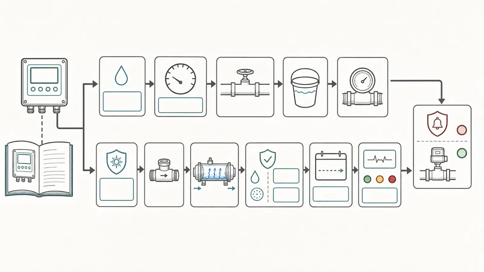
Find the owner’s or installation manual for that exact model. Do not use a manual for a similar-looking unit. Look for these fields:
- maximum or rated flow in US gallons per minute;
- dose basis, such as a stated mJ/cm² value or certification class;
- UVT, transmittance, or absorbance basis;
- maximum turbidity and any iron, manganese, hardness, temperature, or total-dissolved-solids limits;
- operating pressure range and any pressure drop at a stated flow;
- flow restrictor requirement, part number, color code, or factory setting;
- lamp replacement interval;
- sensor, alarm, solenoid, or automatic-shutoff behavior;
- whether the unit is intended for point-of-entry potable water, point-of-use water, or another application.
The VIQUA D4/E4/F4 manual, for example, identifies a sample valve for water entering the chamber, another immediately after treatment, a UV sensor on equipped models, and a flow restrictor intended to prevent flow above the maximum NSF-certified rate. That is a model-family example, not a universal layout. Some units have no upstream sample valve; some have a built-in regulator; some use an electronic flow or dose calculation; and some offer an automatic valve only as an option.
Write the model’s maximum flow in the worksheet before you collect water. If the manual gives different ratings for different UVT values or certification classes, write the applicable basis beside the number. If you cannot identify the model or the manual is missing, do not substitute a generic target such as 5, 10, or 15 GPM. Photograph the label, keep the water-use decision conservative, and contact the manufacturer or a qualified installer.
Do not universalize “40 mJ/cm²”
About 40 mJ/cm² is a common design reference, but it is not a free-standing pass/fail number for an unknown installation. The Drinking Water Inspectorate says the minimum dose is generally taken to be around 40 mJ/cm², while also saying the required dose depends on the microorganism and that manufacturers’ operating recommendations must be followed. Ontario’s government guidance describes 40 mJ/cm² at maximum flow and 75% UVT as part of an equivalency discussion for its systems. Watts’ own tables tie a 40 mJ/cm² dose to particular models, flow values, and UVT values.
The safe homeowner entry is therefore “model manual or certification says ___,” not “all UV units are safe below 40.” Record the source document and page or table number with your result.
3. Measure flow at a safe, useful location
Choose the collection point
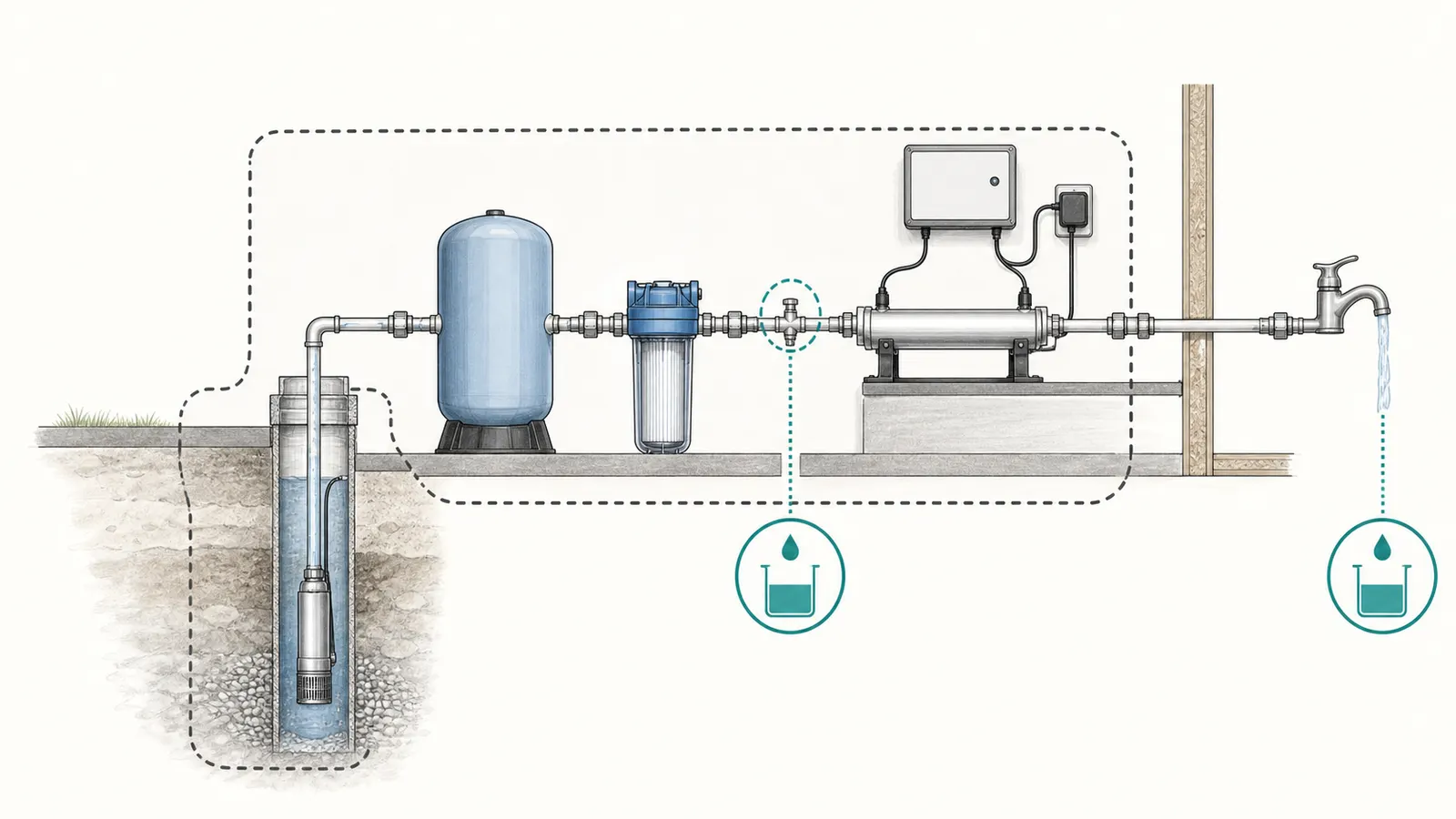
The best homeowner measurement point is an existing sample valve immediately upstream of the reactor, if the installation has one and the manual describes it. That point is close to the reactor inlet and avoids guessing how much flow a downstream faucet aerator, hose, or fixture valve restricts.
If there is no safe upstream sample valve, use a normal cold-water faucet downstream of the UV unit. A downstream faucet test is still useful for household peak-demand screening, but label it honestly: “flow collected at kitchen faucet,” not “reactor inlet flow.” If the reactor has a downstream sample valve, that can show treated-side hydraulic flow, but it still may not equal the flow at the chamber inlet if the plumbing arrangement or sampling valve changes the restriction.
Do not create a sample point by disconnecting a pipe, loosening a fitting, removing a cartridge housing, opening a filter sump, removing a restrictor, or bypassing the reactor. Pressurized water can release unexpectedly, and a UV installation combines water with electricity. The VIQUA manual’s service sequence requires power disconnection, water shutoff, and pressure release before service; that is a clear boundary against improvising a pipe-side test.
Use a clean container with a known volume. A marked 1-gallon container is convenient, but a smaller container can be safer if the sample point has a strong flow. Do not use a container that has held chemicals. Keep the container stable, keep hands away from electrical components, and route spilled water away from the controller, outlet, and floor hazards.
You need:
- a container with a verified volume in gallons;
- a stopwatch or phone timer;
- paper or a note app;
- the model manual and a photo of the label;
- an existing pressure gauge reading, if one is visible without opening equipment;
- another adult if safely coordinating multiple ordinary faucets;
- a way to identify which fixtures were open during each trial.
Calculate gallons per minute
Use this unit conversion:
GPM = gallons collected × 60 ÷ fill time in seconds
Example: if a 1.00-gallon container fills in 12 seconds, the screening result is 1.00 × 60 ÷ 12 = 5.0 GPM. If a 2.00-gallon container fills in 18 seconds, the result is 2.00 × 60 ÷ 18 = 6.7 GPM when rounded to one decimal place.
The result is only as precise as the container volume, start and stop timing, and the stability of the flow. Avoid reporting 6.6667 GPM from a hand-timed bucket test. Record the raw gallons and seconds, calculate to one decimal place, and note whether the flow was visibly steady or pulsing.
Run a low-risk single-fixture trial first
- Confirm that the UV controller has no active alarm, the unit is powered according to its normal display, and no water is leaking near electrical parts. If the controller shows an alarm or the area is wet, stop.
- Choose the collection point. If using a faucet, remove only a readily removable aerator if that can be done without tools, splashing, or disturbing the plumbing; otherwise leave the fixture as installed and record it. Do not disassemble a valve or pipe.
- Run cold water long enough to clear standing water in the fixture. Do not drink the sample. If the manual specifies a flush time or a sample-valve procedure, follow the manual.
- Place the container under the outlet. Start the timer as the container begins filling and stop it at the marked volume. Record gallons, seconds, fixture, and any visible pressure-gauge reading.
- Repeat the same trial at least once. If the two results differ materially, run a third trial and note pulsing, pump start, pressure change, or a partially open valve.
This first trial is a sanity check. It can reveal a clogged aerator, an unexpectedly weak outlet, or a timing error. It is not the household peak.
4. Repeat the test at real peak demand and relevant pressure
A point-of-entry UV reactor must be sized for the water that can pass through it when people use the home, not just for the kitchen faucet. The test should therefore include the highest realistic simultaneous demand you can create with ordinary fixtures: for example, a shower plus a toilet refill plus a laundry or utility faucet, or the combination your household actually produces. Do not run appliances or fixtures that could overflow, scald, or create a slip hazard merely to make a larger number.
The exact combination is a household observation, not a universal fixture-unit calculation. Record what you opened and why it represents peak use in your home. If an irrigation branch, barn line, hose bib, or rental unit shares the treatment train, include it only if it can draw through the UV unit and is part of the design scope. If the UV system serves only drinking water at a point of use, do not test whole-house demand against it.
A practical simultaneous-demand procedure
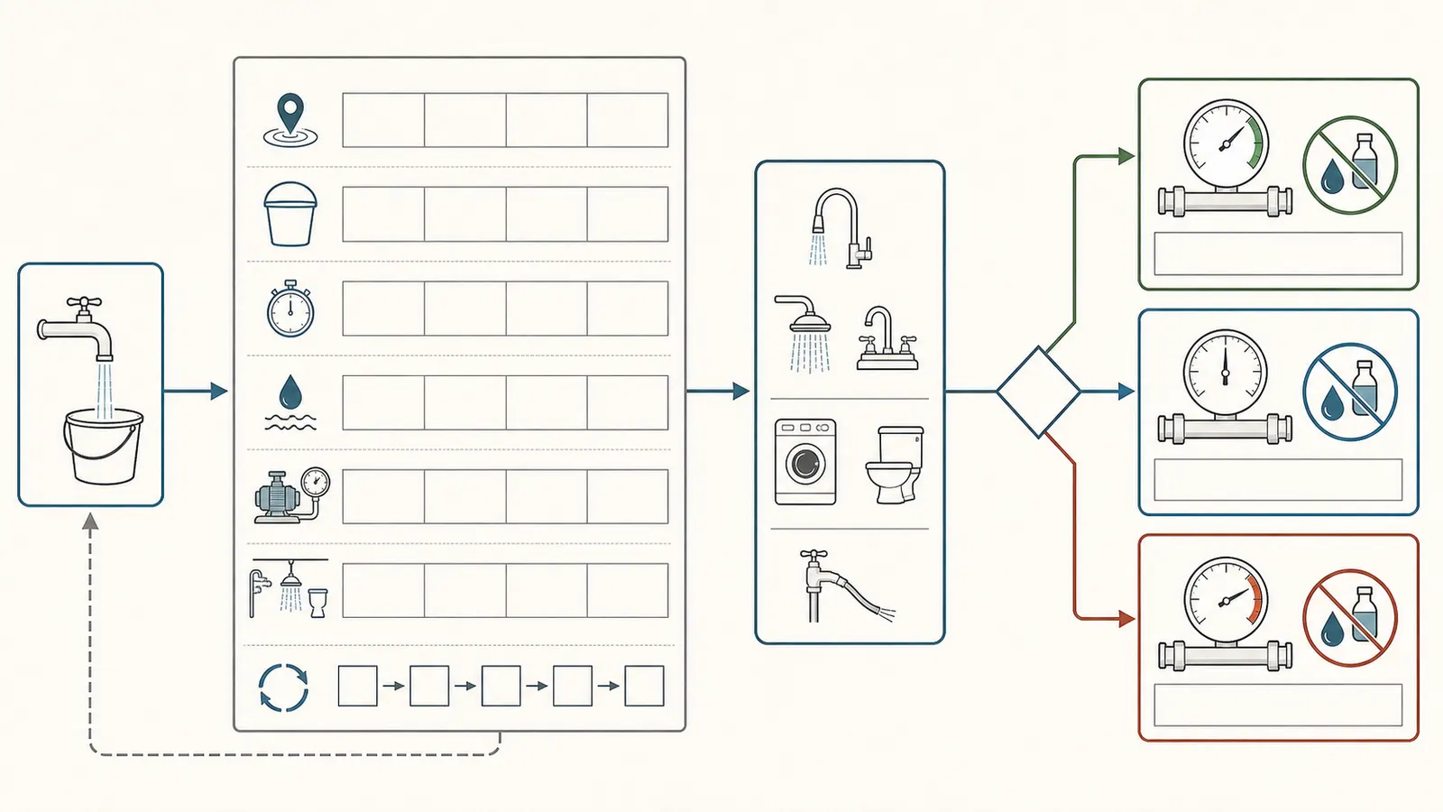
- Start with the reactor in normal service and all ordinary fixtures closed.
- Open the chosen simultaneous fixtures one at a time. Keep them at the normal positions used by the household; do not force a valve fully open if that creates a flood or unsafe discharge.
- At the selected collection point, time the same known container volume. If the outlet is one of the open fixtures, use a second safe collection point or have the second person coordinate the fixtures.
- Record the pressure-gauge reading if a gauge is already installed and visible. Record whether the pump was running, had just started, or the pressure was falling. Do not adjust the pressure switch, tank precharge, relief valve, or any control to create a test condition.
- Repeat the trial. If the pump cycles during the fill, record the start and end pressure if visible and treat the result as a range rather than a single stable number.
- Close the fixtures normally and check from the outside for leaks, alarms, unusual noises, or a wet floor. Do not open the electrical enclosure to investigate.
Do not let one faucet undercount a point-of-entry reactor
If this is a point-of-entry UV unit, timing only the faucet under the bucket while other fixtures are open is not a peak-flow measurement. The other fixtures are also taking water through the reactor, so the timed outlet can look safely below the model rating while the total reactor flow is higher. A downstream faucet result by itself is therefore a partial reading, not a hydraulic pass.
When there is no safe upstream sample valve, use one of these complete methods:
- Sum the simultaneous downstream outlets. Keep the selected fixtures at the same settings. With a helper maintaining the demand, measure each safely collectable outlet one at a time using a verified container and the same timing method while the other fixtures remain open. Calculate each outlet’s GPM, then add the readings. Record every outlet, including any that could not be collected. Do not place a container under a toilet refill, appliance connection, hot or scalding discharge, outdoor hose, or any outlet that creates a spill or electrical hazard.
- Use a whole-house meter or totalizer. If an existing meter or totalizer captures all water leaving the UV reactor, record its reading at the start and end of a timed interval while the same simultaneous demand remains open. Calculate
GPM = gallons shown by the meter change × 60 ÷ interval seconds. Exclude any branch the meter does not measure and record its resolution. Do not install, move, or open a meter to create this test. - Require an inlet measurement. If any active branch cannot be safely measured and no totalizer captures it, do not call the result a hydraulic pass. Arrange for the manufacturer, installer, or qualified water-treatment professional to measure flow at the reactor inlet with appropriate equipment. A single downstream faucet can still document that outlet, but it cannot clear the whole-house reactor flow.
Repeat the complete sum or totalizer method at the naturally occurring high and low normal pressure conditions described below. If you cannot repeat the total at those conditions, record the result as inconclusive and use the professional-measurement path. Never create a larger demand by opening a pressurized fitting or altering a control.
Test high and low normal pressure without manipulating equipment
Pressure is relevant because flow can change as a pressure tank draws down, a pump starts, a filter loads, or a restrictor creates pressure loss. A homeowner can capture this variation by repeating the demand test during normal operation at two naturally occurring conditions: one trial while the pressure gauge is near the upper part of its ordinary cycle and another while it is near the lower part, if both occur without adjustment. If the pump does not cycle during the trial, record that fact.
This is a screening design, not permission to force the pump to run continuously or to alter the pressure switch. Watts publishes operating pressure and pressure-drop values alongside model flow and dose data, and its manual notes that a flow restrictor changes pressure drop. That is why a single faucet result at a single pressure should not be treated as the whole installation’s hydraulic envelope.
If the household demand produces a low-pressure symptom, banging, short cycling, loss of prime, sputtering, or a pump that does not recover, stop the test. Those symptoms belong to a well-pump or plumbing diagnosis, not to a more aggressive UV experiment. Bring the recorded fixtures, times, pressure observations, and UV model to a qualified well or water-treatment professional.
Worksheet: record the raw evidence
| Trial | Collection point | Container gallons | Fill seconds | Calculated GPM | Fixtures open | Pressure observation | Pump state | Alarm/status | Notes |
|---|---|---|---|---|---|---|---|---|---|
| 1 | |||||||||
| 2 | |||||||||
| 3 | |||||||||
| 4 peak demand | |||||||||
| 5 peak, other normal pressure |
For the decision, use the highest credible total flow observed during realistic simultaneous demand, not the most convenient single-faucet result. If the trial was taken downstream of the reactor, label whether it is a complete sum, a totalizer reading, or only one outlet. A single-outlet reading cannot support a point-of-entry hydraulic pass. If the flow was pulsing, report the range or repeat the complete measurement with professional equipment rather than disguising instability with a rounded average.
5. Compare the result with the exact model’s operating basis
Put the measured result next to the manual’s maximum flow, not next to a generic “UV systems usually handle” number.
| Evidence item | Your record | Decision use |
|---|---|---|
| Brand, model, serial | Confirms which manual and table apply | |
| Model-rated or validated maximum flow | The upper hydraulic boundary in the stated dose basis | |
| Highest credible measured flow | Compare only after noting collection point and pressure condition | |
| Dose basis | Record mJ/cm², certification class, or exact manual wording | |
| UVT requirement | Water must transmit enough UV for the model’s basis | |
| Turbidity and pretreatment limits | Cloudiness and particles can shield organisms and foul the sleeve | |
| Flow restrictor required? | Confirm presence and model-specific identity; do not remove it | |
| Lamp age and replacement date | A glowing lamp may still be past its service life | |
| Sensor, monitor, alarm, shutoff status | A safety control can change the water-use decision |
Three hydraulic outcomes
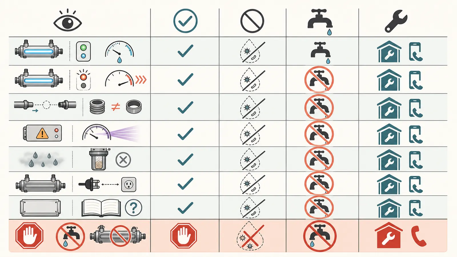
Below the rated maximum with stable repeats. This supports a hydraulic pass only when the result is an upstream reactor-inlet measurement, a totalizer that captures all reactor flow, or a documented sum of every safely measurable downstream branch. A single downstream faucet cannot support that conclusion. The result still does not certify dose. Proceed to the water-quality, lamp, restrictor, and control checks below. A margin below the published maximum is useful evidence, but do not invent a universal margin or subtract an arbitrary percentage unless the manual or engineer specifies one.
Near the rated maximum, incomplete, or unstable. Treat this as a caution result. Timing error, pressure variation, container error, filter loading, an unmeasured branch, and a partially closed valve can move the total across the boundary. Repeat the complete sum or totalizer method with a larger verified container, or have a professional measure flow at the reactor inlet. Ask the manufacturer whether the rating assumes a restrictor, a specific pressure, a particular UVT, or a particular certification test. Do not call it safe merely because one rounded faucet result is 0.1 GPM below the rating.
Above the rated maximum. The installed unit is being asked to operate outside the model’s stated flow basis. Close the demand to restore ordinary service only if doing so is safe, then stop using the water for drinking and cooking until the manufacturer or qualified professional verifies the arrangement. Do not solve the result by drilling, removing, or replacing a restrictor with an unapproved part. The Watts manual states that removing a restrictor can let flow exceed validated performance and may prevent the necessary UV dose.
A manufacturer example, not a target
Watts’ UV-COM tables show why model identification matters. Its C196C sheet lists a 16.5 US GPM maximum flow and its C222C sheet lists 27.4 US GPM; both tie those figures to a 40 mJ/cm² minimum dose, a stated operating-pressure range, UVT, and model-specific pressure drop. Those numbers cannot be applied to a different reactor, lamp, UVT basis, or certification class. They are examples of the evidence you should find in your own manual.
VIQUA’s manual likewise distinguishes standard, 50%-UVT, and NSF Standard 55 Class B model families and lists different water-quality parameters and restrictor arrangements. The lesson is not that one brand is better. It is that model, certification, water quality, and flow must stay attached to one another in the record.
6. Check the restrictor, water quality, lamp, and alarms separately
Hydraulic flow is only one gate. Complete these checks without opening energized equipment or pressurized housings.
Flow restrictor: look, do not remove
If the manual calls for a supplied or built-in flow restrictor, compare the visible installation with the manual’s diagram or parts list. Photograph the marking or part number if accessible from the outside. Check whether the restrictor appears to be installed in the intended location and whether there is evidence of an unapproved bypass or recent plumbing change.
Do not loosen the restrictor, pull it from a fitting, drill it, clean it with a wire, or substitute a “same-size” part. Restrictors are not interchangeable by appearance. The Watts manual says a restrictor limits flow despite demand or supply pressure and is mandatory for its NSF/ANSI 55 Class models. The VIQUA manual describes its restrictor as preventing flow above the maximum certified rate. If the restrictor is missing, damaged, or unidentified, treat the unit as unverified and contact the manufacturer or installer.
Water clarity, UVT, and pretreatment
A clear glass is not a UVT measurement. UVT is a laboratory or instrument value describing how much UV light passes through the water. Turbidity is a measure of cloudiness or suspended particles. Both can vary with a filter backwash, softener regeneration, well disturbance, seasonal conditions, or a plumbing change.
The Drinking Water Inspectorate notes that particles can shield microorganisms and foul the lamp sleeve, and that UV equipment manufacturers commonly specify minimum UVT values. The VIQUA manual and Watts manual each list turbidity and UVT parameters for particular model families. Use the exact model’s limit. Do not infer that water is within UVT simply because it looks clear, and do not infer that a sediment cartridge makes every UVT problem disappear.
If the unit has a low-UV, dose, or UVT alarm, follow the manual’s troubleshooting sequence. The Watts manual says its dose alarm can result from low UV intensity, low UVT, or both and recommends a UVT sample to confirm the prediction. The VIQUA troubleshooting path names pretreatment-filter checks, flushing, sleeve and sensor cleaning, UVT testing, and lamp or sensor checks for its equipped models. Those are model-specific service paths; a homeowner should not open the chamber or sensor assembly unless the exact manual’s procedure makes the action safe and the water and electrical hazards are controlled.
Lamp age and sleeve condition
Record the lamp installation date or controller lamp timer. A lamp can look bright and still be outside its effective service life. The Drinking Water Inspectorate says lamp output decreases with age and that visible light is not proof of required dose. The VIQUA manual specifies annual replacement for continuous operation in the cited model family and warns that non-genuine replacement lamps can damage the controller, create a safety risk, and lack equivalent performance even when blue light is visible.
Do not look directly at an exposed UV lamp, operate a lamp outside its chamber, or remove the lamp to see whether it is working. UV radiation can injure eyes and skin, and the chamber can remain hot or pressurized. Lamp replacement and sleeve cleaning are service procedures: follow the exact manual, or use qualified service if the procedure includes pressure release, electrical disconnection, mercury-containing lamp handling, or a leak risk.
Alarm and automatic shutoff
Read the controller status before and after the flow trials. Record normal, warning, alarm, lamp timer, sensor status, and any displayed UV intensity or UVT value. Do not mute an alarm and call the flow test complete.
If the system has a homeowner-testable alarm or automatic shutoff procedure in its manual, follow that procedure exactly. Some systems use a solenoid or automatic valve; others only sound or display an alarm. Ontario guidance recommends checking automatic shutoff and alarm functions on a recurring schedule where the applicable maintenance documents do not specify another requirement, but that schedule is Ontario program guidance rather than a national US rule. The installed manual and local requirements control.
Never unplug a wet controller, defeat a safety interlock, jumper a relay, or reach into a panel. If testing the alarm requires loss of power or a service mode, have a qualified professional perform it unless the manufacturer’s homeowner procedure expressly covers the exact action.
7. Make the safe next decision and hand off the evidence
Use this decision matrix after the measurements.
| Observation | What it supports | What it does not prove | Safest next step |
|---|---|---|---|
| Peak measured flow is below exact model rating; no alarm; lamp and pretreatment records are current | Hydraulic demand is within the stated flow boundary for the tested conditions | Microbiological safety, current UVT, correct installation, or future peak flow | Keep the record, follow the manual’s maintenance schedule, and obtain lab or professional confirmation if any condition is unknown |
| Flow is near the rating or changes with pressure | The installation may need a more controlled inlet-flow test | That the rounded bucket result is safely below the boundary | Repeat with documented pressure conditions or ask a qualified professional to measure at the reactor |
| Flow exceeds the rating | The reactor is outside its stated hydraulic basis during that demand | That a restrictor removal or lower-use workaround is safe | Stop drinking and cooking use until the model, restrictor, and design are reviewed; contact manufacturer or qualified service |
| Restrictor missing, wrong, bypassed, or unidentified | The installation’s flow control is unverified | That the chamber can deliver its rated dose without it | Do not modify it; contact manufacturer, installer, or qualified water-treatment professional |
| Low-UV, dose, sensor, lamp, or power alarm | Treatment status is abnormal or unconfirmed | That the bucket result overrides the alarm | Stop drinking and cooking use; follow the manual’s troubleshooting and use qualified service |
| Water is cloudy, visibly turbid, or pretreatment is bypassed or failed | The model’s water-quality basis may not be met | That clear water later will be safe without testing | Stop use for drinking and cooking, correct pretreatment through qualified service, and obtain model-appropriate water testing |
| Model, dose basis, UVT limit, or lamp date is unknown | The evidence trail is incomplete | That a generic online flow table applies | Photograph labels and contact the manufacturer or a qualified professional |
| Bacterial sample is positive downstream of UV | There may be a treatment, plumbing, sampling, or recontamination problem | That raising or lowering GPM alone will solve it | Use a known-safe alternative and contact the lab, health department, manufacturer, and qualified well professional |
Stop-use boundary
For this worksheet, “stop using the water” means stop using it for drinking, cooking, ice, brushing teeth, infant formula, and other ingestion-related uses until a qualified source confirms a safe alternative or the system is restored and verified. Use bottled or otherwise known-safe water during the review. Do not assume that boiling repairs a UV system, because boiling does not correct every possible contaminant and may be inappropriate for a specific advisory.
If the failure involved a bypass, lamp change, power outage, opened plumbing, or contamination downstream of the UV unit, ask the manufacturer or a qualified well professional whether the plumbing needs disinfection and whether repeat microbiological testing is appropriate. The VIQUA troubleshooting table separately identifies downstream equipment, post-UV distribution lines, and pipe dead ends as possible sources of bacterial contamination and gives model-specific corrective actions. That is why a hydraulic pass cannot be treated as a water-safety certificate.
What to give the professional
Send one compact packet instead of a vague request to “check the UV.” Include:
- a photo of the controller and chamber labels;
- brand, model, serial number, certification marking, and manual revision;
- model-rated maximum flow and dose basis with the manual page or table;
- UVT, turbidity, pressure, temperature, and pretreatment limits;
- restrictor marking or a note that it could not be identified without disassembly;
- lamp installation date, sleeve-cleaning date, sensor status, and recent alarms;
- every raw flow trial: container volume, fill seconds, calculated GPM, collection point, fixtures open, pressure observation, and pump state;
- whether the sample point was upstream, downstream, or an ordinary faucet;
- recent filter changes, softener regeneration, well work, power interruptions, flooding, or plumbing changes;
- laboratory reports, especially UVT, turbidity, coliform, nitrate, and any contaminant relevant to the household;
- the safe-water decision already made while the issue is unresolved.
Ask the professional to answer five questions in writing: Is the measured peak flow at the reactor within the exact model’s validated rating? Is the restrictor correct and functional? Are UVT, turbidity, pretreatment, pressure, and temperature within the model basis? Are lamp, sensor, alarm, and shutoff controls operating as designed? What maintenance or retesting proves the next decision?
The finished worksheet should end with one of three honest statements: “Hydraulic screening passed; other UV conditions still to be verified,” “Hydraulic result is inconclusive; professional measurement required,” or “System is outside its model or safety basis; drinking-water use stopped pending correction.” That evidence trail is more useful than a bucket number alone, and it keeps measured flow separate from proof that the water is microbiologically safe.
Sources and scope
Evidence behind this page
- Drinking Water Inspectorate — UV disinfection
Government guidance for private water supplies in England; supports the technical distinction between hydraulic flow screening and validated UV dose, not a universal US private-well rule.
- Drinking Water Inspectorate — UV disinfection
Government technical guidance; the maintenance and flow boundary is general safety guidance, while exact limits belong to the installed manufacturer model and applicable certification.
- U.S. Environmental Protection Agency — Ultraviolet Treatment Toolkit
EPA technical resource for states evaluating UV technology; supports the distinction between a homeowner hydraulic screen and validated operating conditions, but is not a universal private-well rule or a substitute for the installed model's manual and certification.
- Drinking Water Inspectorate — UV disinfection
Government private-supply guidance; supports a conservative stop-use branch and does not establish a particular alarm test frequency for US homes.
- VIQUA — D4 Premium, E4, F4 and validated models Owner’s Manual, Rev E
Specific VIQUA model family manual; use as an example of model-specific components and sampling locations, not as a claim that every UV system has the same layout or restrictor.
- VIQUA — D4 Premium, E4, F4 and validated models Owner’s Manual, Rev E
Specifications for the named VIQUA model families; values must not be generalized to another brand or model.
- VIQUA — D4 Premium, E4, F4 and validated models Owner’s Manual, Rev E
Specific VIQUA maintenance and safety instructions; the article uses them to define hazardous work and to require the exact manual for other equipment.
- VIQUA — D4 Premium, E4, F4 and validated models Owner’s Manual, Rev E
Manual Section 6, Troubleshooting table, PDF pp. 22–23; supports this VIQUA model-family contamination explanation only and does not establish a universal diagnosis for every UV installation.
- VIQUA — D4 Premium, E4, F4 and validated models Owner’s Manual, Rev E
Manual Section 6, Troubleshooting table, PDF pp. 22–23; a source-specific post-UV plumbing troubleshooting path, not permission for a homeowner to chlorinate plumbing without applicable instructions or professional guidance.
- VIQUA — D4 Premium, E4, F4 and validated models Owner’s Manual, Rev E
Manual Section 6, Troubleshooting table, PDF pp. 22–23; applies to the cited VIQUA troubleshooting guidance and is not a universal finding or homeowner plumbing instruction.
- VIQUA — D4 Premium, E4, F4 and validated models Owner’s Manual, Rev E
Manual low-UV alarm screens and Section 6.1, PDF pp. 15 and 23–24; supports the article’s model-specific troubleshooting example and does not replace the exact manual for another controller.
- VIQUA — D4 Premium, E4, F4 and validated models Owner’s Manual, Rev E
Manual opening replacement-lamp notice, PDF pp. 2–3; applies to the cited VIQUA model family and is not a claim about the replacement policy or warranty of another manufacturer.
- Watts — UV-COM Ultraviolet Water Disinfection System Installation and Operation Manual
Watts UV-COM model family; supports the restrictor inspection decision and must not be treated as a universal component specification.
- Watts — UV-COM Ultraviolet Water Disinfection System Installation and Operation Manual
Examples from Watts UV-COM performance data sheets; the numbers are not a sizing recommendation for an unidentified unit.
- Watts — UV-COM Ultraviolet Water Disinfection System Installation and Operation Manual
Watts UV-COM alarm logic; supports the article’s separate alarm and water-quality branch, not a claim that every controller uses the same alarm name or display.
- Ontario — Using ultraviolet disinfection at drinking water systems
Ontario regulatory and operational guidance for non-municipal year-round residential or designated-facility systems; the three-month example is not a US national rule and the installed manual controls.
- Ontario — Using ultraviolet disinfection at drinking water systems
Ontario program guidance; these values are presented as jurisdiction-specific equivalency guidance, not a universal US private-well clearance or a substitute for the model’s certification documents.
- Brictale calculation based on US customary units
Arithmetic and measurement scope defined in this article; the linked government source supports why flow is one dose input, while the calculation does not certify microbiological performance.